


Hardware components | ||||||
 |
| × | 2 | |||
 |
| × | 2 | |||
| × | 1 | ||||
| × | 2 | ||||
| × | 2 | ||||
| × | 1 | ||||
| × | 1 | ||||
| × | 1 | ||||
Software apps and online services | ||||||
 |
| |||||
Hand tools and fabrication machines | ||||||
| ||||||
| ||||||
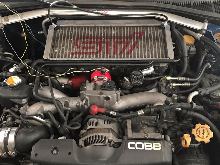
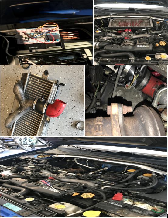
The problem addressed in this project is that intercoolers function at a certain temperature and while they can function properly at normal operating temperatures, the higher the temperature of air across the intercooler the more a vehicles performance can suffer. The vehicles performance suffers due to warmer air being less dense which in return requires the force induction component to work harder. Sense the intercooler is responsible for decreasing the temperature of charged air being input, it is important to keep temperatures across the intercooler as low as possible for maximum performance and efficiency.
SolutionThe solution to lowering the temperature across an intercooler was to implement a device to spray or mist the intercooler to control the temperature. This was accomplished by running a cold reservoir of liquid from the inside of the car through the firewall to where it would then be focused with nozzles over the intercooler to mist it and control the temperature. There would be two temperature sensors placed before the intercooler inlet and the outlet. This way we could have an accurate temperature difference calculation based on what temperature the inserted air was and what temperature the charged air exiting was. This entire project would be controlled by our particle photons that were purchased for the class. For the above steps to work one of the particle photons would measure the temperatures of the intercooler while the other would give a visual display on a LCD screen. Below is a sketched drawing of the system implemented.
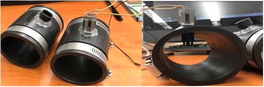
The components necessary for completion were two temperature sensors and a windshield whipper reservoir and pump acquired from a pick and pull. Two 2x2 inch rubber plumbing couplets from Home Depot as well as to IOT kits purchased online; various components of this kit were used. Once the required parts were obtained the assembly began with the two temperature sensors being placed in the rubber plumbing and attached to the corresponding places of required measured temperatures. Followed by the running a line to pump water from the whipper reservoir from the inside of the car into the engine bay. This step was followed up with the necessary wiring as well as a thorough inspection. While the hardware was being assembled the two codes for both particle photons was also being created.
Attached below is a YouTube video that demonstrates the device and the two particle photons working to produce the solution described above.
ConclusionAfter testing the constructed device, it was clear to see that the temperatures were decreased and therefore the prototype device can be concluded a success. Although the temperatures were decreased it should be mentioned that while the temperatures were decreased, the amount they decreased by was not significant enough to give an increase in performance strong enough for the driver to notice. This is since for every 10 degrees Fahrenheit (5.5556 Celsius) the expected horsepower gain is one. Therefore, the temperature drop would have to be very significant in order to supply enough power for the driver to notice and to offset the new power to weight ratio sense weight was added by the new device. Another conclusion from this project is the power of the particle photons and what they can be used for. Through this project alone it is clear to see that the particle photon can be used to control or have input on almost anything that is electrical on a vehicle and due to its abilities to connect to wifi it can be used almost anywhere.
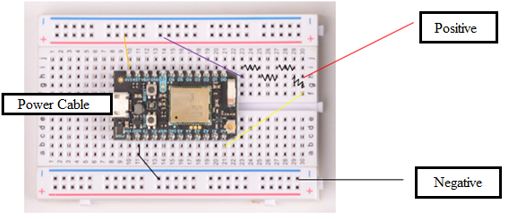
Circuit 1. Transmitter Configuration
ORANGE LINE-Connects from particle photon pin 3v3 to positive terminal
PURPLE LINE-Connects from particle photon positive terminal to 22k ohm resistor
RESISTORS-The resistors in series are 22k,1k,10k, and 2.2k ohm resistors.
RED LINE-Connects to end of resistors in series to positive power supply
YELLOW LINE-connects from particle photon pin A0 to end of resistors in series
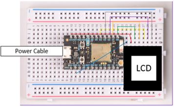
Circuit 2. Receiver Configuration
RED LINE-Connects from particle photon pin 3v3 to LCD pin VCC
GREEN LINE-Connects from particle photon pin D0 to LCD pin D0
ORANGE LINE-Connects from particle photon pin D1 to LCD pin D1
Yellow LINE-Connects from particle photon pin D4 to LCD pin RST
PURPLE LINE-Connects from particle photon pin D2 to LCD pin DC
GREY LINE-Connects from particle photon pin D3 to LCD pin CS
Temperature Sensors


Comments
Please log in or sign up to comment.