The ESP8266 has long been a preferred tool for IoT project due to it's cheap price and growing support. This project contains two ways to create an internet connected power strip that interfaces with an Amazon Alexa/echo device.
Before diving into code, make sure you have installed the necessary libraries:
Arduino ESP8266 board managers: File > Preferences > Additional Board Manager URLs: http://arduino.esp8266.com/stable/package_esp8266com_index.json
Install ESP8266 Libraries: Sketch > Include Libraries > Manage Libraries... > ESP8266
Smart Home Method (Easy)This method emulates multiple WeMo devices on the ESP8266 using the FauxMo library.
Pros:
- Easy to set up. Edit Wifi credentials, update device names, and flash onto esp board.
- Simple utterance for device control: 'Alexa, turn the {device name} on/off'
Cons:
- Limited control. Can only toggle on/off.
- Limited response. Alexa always responds with 'ok'.
- Possible loss of support with device updates
- Only supported by devices with control over UDP (google home does not work)
Instructions:
- Open smartPowerStrip\code\Smart Home\multiFauxMo.ino and edit the relevant parameters; ssid, password, pin numbers.
- Select the correct board on the arduino IDE and flash. You're now ready to rock. You can rename the switches in your Alexa app.
With this method, the ESP device polls DynamoDB for values, parses the data, and handles the necessary hardware peripherals. The code is also able to update a value (or write a whole new entry) to handle cases where the user wants to update a value via hardware. Using this method gives us the ability to pass more than binary states to our ESP device, opening the door to all kinds of applications.
Pros:
- Unlimited control and customization. Can read multiple values and datatypes from DynamoDB.
- No need for middle-ware like a MQTT broker. ESP device communicates directly with the cloud.
- Can have custom, elaborate responses from Alexa.
Cons:
- More difficult setup. Needs to create DynamoDB, install ArduinoAWS libraries, and setup Lambda Function.
- Longer utterance: 'Alexa, tell {skill name} to {intent}'
Common issues:
- Values in DynamoDB are not Strings. Check that the value's are not Number format.
WARNING: If you're not comfortable handling 120VAC don't try this build. Certain loads connected to the power strip could potentially be permanently damaged when dimmed, the system was tested with incandescent bulbs and heaters.
1. Hardware:The enclosure was designed with shelving capability to separate the high voltage components from the low voltage ones. The power line was placed on the bottom corner of the face to allow for strain relief to be installed and a slot was added to allow for re-programming of the ESP chip. After printing, an acrylic sheet was cut with a notch on the side to be used as a shelf support and allow wires to be run between levels. The electronics were assembled, the receptacles were inserted into the appropriate slots, and then soldered to the power leads coming from the dimming module. The cover was then attached to the housing using six M4 screws.
To perform AC dimming with a MCU we need a circuit that can handle switching AC voltages and another circuit to tell the controller when the AC wave has crossed zero. For details on the theory view the Useful Links section.
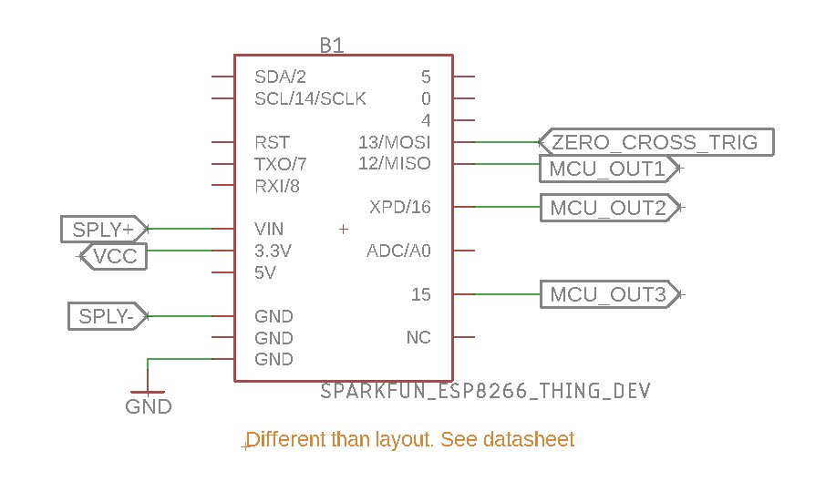
The circuit that was designed detects when the AC wave crosses the zero point and sends a signal to the ESP device while under optical isolation. The ESP device then counts how many milliseconds have elapsed and toggles a GPIO at the appropiate time. The GPIO outputs to an MOC3020M which optically isolates the MCU device from the high voltage. This signal closes the gate of the TRIAC and let's voltage flow through, turning on the device. A PCB schematic was created, layed out, and sent for manufacture to minimize the footprint of the electronics.
The PCB was assembled and connected to an ESP8266 Thing Dev and an AC-DC Converter from an old iPhone charger. The AC-DC converter connects to a standard 120VAC cable and powers the electronics.
The main hurdle with coding this program is the real time control part. The ESP8266 is not designed for real time control so we have to do some acrobatics to get it to perform dimming. The internal clock for the ESP runs at 80Mhz (by default) and we can piggy back off this clock to run the dimmer interrupt. Because this interrupt will run every few microseconds it has to be fast. For this reason, we must add the ICACHE_RAM_ATTR directive to our interrupt function to place it in RAM instead of FLASH; not a very well documented directive. The accuracy of this interrupt seems to be +-3us, a negligible error for this application. Below is a diagram of how the code is structured.
Create a DynamoDB table with a Partition name as a String and a Sort key as a Number then create a new item for the table. To follow this repo use devName (String): ESP8266, devID (Number): 1, onStatus (String): 1, and brightLvl (String): 100.
Navigate to AWS site > IAM and create a user with full access to DynamoDB. This will be used to give the Lambda Function the ESP device read and write privileges. Now we can work on the embedded code
Download ArduinoAWS Libraries and copy them to arduino installation directory. In a windows machine C:\Program Files (x86)\Arduino\libraries. For more details, go here
Open the smartPowerStrip\code\AlexaSkillsKit\Embedded Code\Esp8266DynamoDB directory and copy the keys corresponding the the user created on IAM.
Edit the code where relevant; AWS_REGION, TABLE_NAME, pSSID, etc. and flash your device. If you're interested to know how the code works, you can go to the Embedded Code section.
The ESP device should now be able to fetch and push to the cloud! Let's add Alexa to the mix
5. Lambda Function:The Lambda Function will be the middleman between the DynamoDB and the Amazon Echo device. Navigate to AWS site > Lambda > Functions > Create function. Assign it the previously created IAM role
Open up AlexaSkillsKit\LambdaFunc\index.js and edit any relevant parameters; tableName, partitionKey, etc. Once that is done, copy index.js and AlexaSkill.js into the Function code section.
Configure the test event by copying testEvent.js into the test event section of the Lambda Function. By default, the test event simulates an Amazon Echo device being told to turn a lamp to 50% brightness.
From the drop down menu, select the test event created, save your code and hit the test button. The database will update with the value in the test event. You can check the Execution Result for more details.
Now we can add an Alexa Skills Kit as a trigger for the Lambda Function. The Disable Skill ID checkbox can be left unchecked.
On the Amazon Developer website, create an Alexa Skills Kit skill. I suggest making the invocation name something easy to remember like, 'The House'.
Configure the Interaction Model based on the files in smartPowerStrip\code\AlexaSkillsKit\speechAssets. Remember to also add in the Custom Slot Types at the bottom of IntentSchema.json and the Sample Utterances provided in the text file.
On the Configuration tab, select AWS Lambda ARN as the endpoint and paste your Lambda function's ARN. This will tie your custom skill to the Lambda Function created.
Test the function by entering an utterance in the Service Simulator, 'dim the lamp to 50 percent'. DynamoDB will update and the ESP device will fetch the latest information. Now you have made your own dimming power strip!
7. Voice User InterfaceThis diagram details the different commands and command trees for our build of the Smart Strip. The end user can follow this diagram and activate the desired functionality of the project.


_nUF0r47aKJ.png)
_nIa7Q6GPnb.png)


_3u05Tpwasz.png?auto=compress%2Cformat&w=40&h=40&fit=fillmax&bg=fff&dpr=2)
Comments
Please log in or sign up to comment.