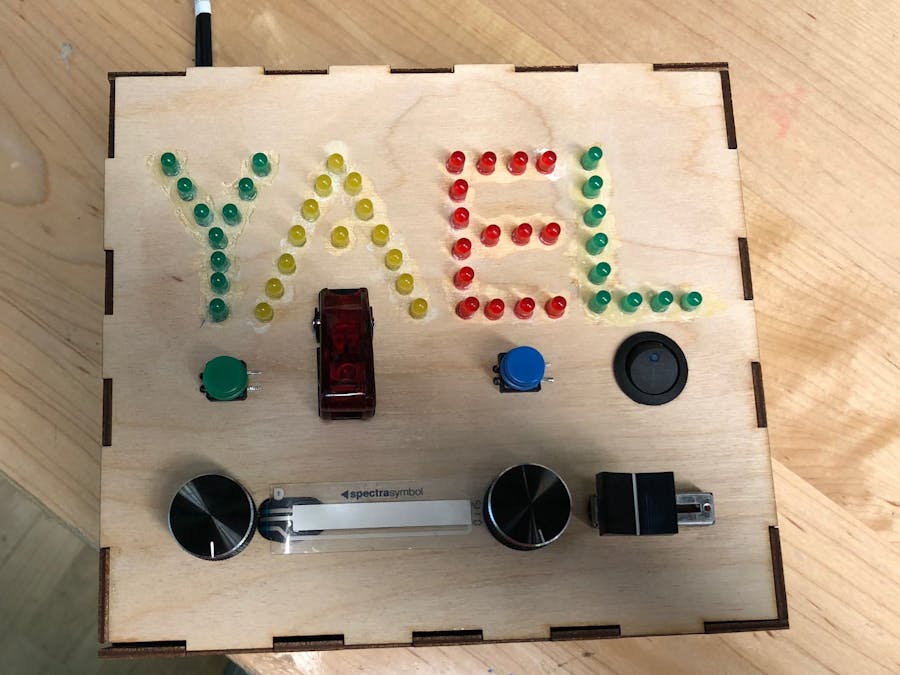
This toy was created for our Physical Computing Class. The main goal of the project was to make an "interactive children's toy," so we decided to create a switch toy with different potentiometers and switches that would entertain children.
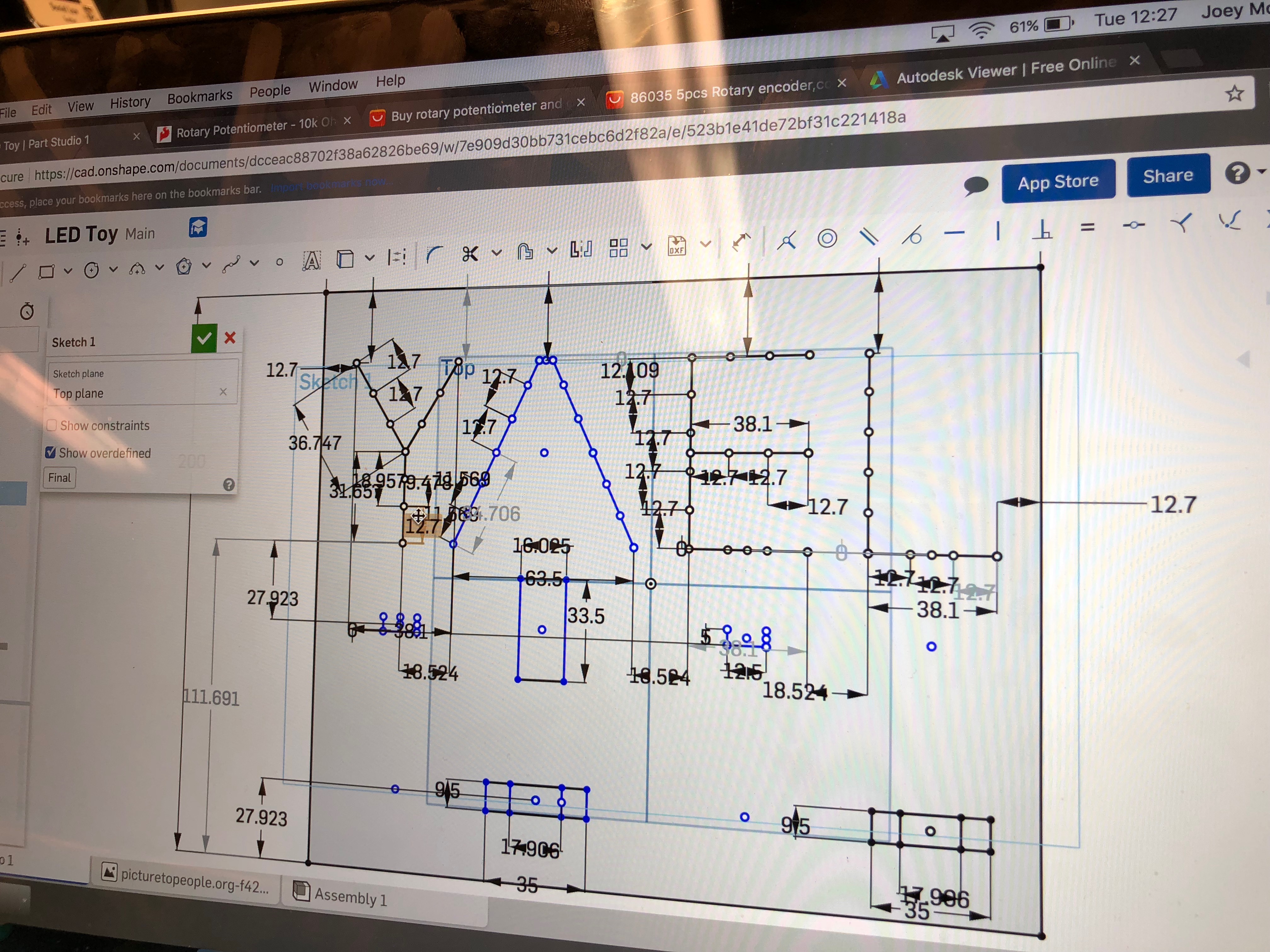
The first thing we did was create an online 3D model of the box our switch toy was going to be created in using onShape. After finishing this we created the toy using our school's laser cutter.
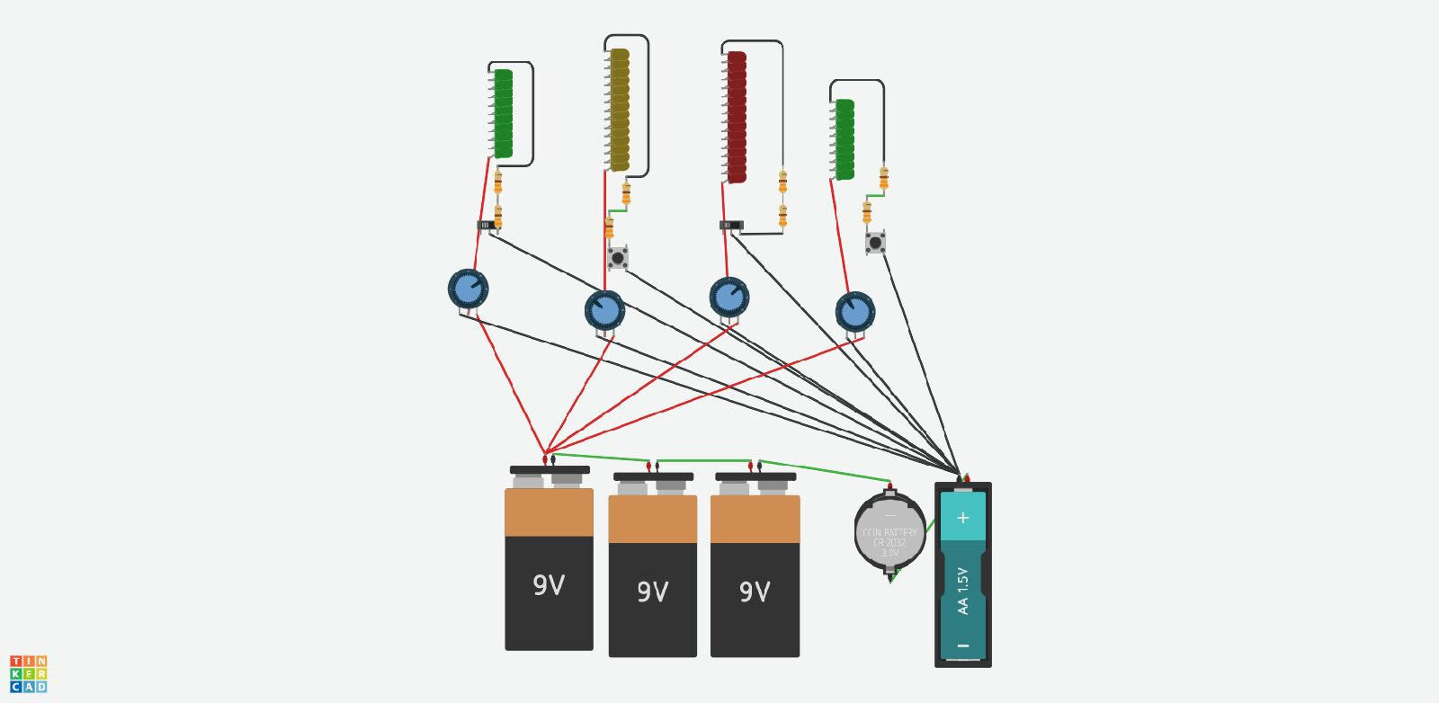
The next step in our project was to create a wire diagram. And then revise it and create a new one. The first one technically worked, but required four 9v batteries to work, which is ridiculous for a kids toy. The working diagram shows 5 batteries but we really just used a 32v power supply. This is probably the hardest part of the project, because it requires more than a basic understanding of series and parallel series, as well as being able to figure out the level of resistor needed for the number of LEDS you're using.
The next step in our project was to glue the LEDs. on to the container while waiting for our parts to arrive. The LEDs were glued on using super glue followed by baking soda to make them dry faster. Make sure to test your LEDs before doing something as permanent as super gluing them to wood, because we forgot to and paid for it later.
After waiting a month for our parts to arrive, the next step was to actually attach all of our parts. When making our CAD profile, we underestimated our mounting hole on purpose, that way we could edit them how we saw fit. Using a drill we slowly made the holes bigger until we could super glue the different parts in.
Tinkercad allowed us to test wiring on every switch and potentiometer except for the soft pot. So, the next step in our project was to figure out the wiring for this, which was very simple, and almost exactly the same as the other potentiometers.
The next step was to follow our Tinkercad wiring diagram and attach everything to eachother. This was accomplished by many hours of soldering and testing so be prepared to put some time into this project. This isn't hard, however, because you should be able to follow your wiring diagram exactly.
After testing the project to make sure everything works correctly, the last step is to glue the box together, drill a hole for a power source (if yours plugs into the wall or is a USB), and show off your new switch toy :).


Comments
Please log in or sign up to comment.