This was a project I made last year for my engineering class that I want to share with the world.
We were assigned with creating a cheap, portable, and affordable device that could help those in Northern India, who don't have access to clean water, reliable electricity, or a light source at nighttime.
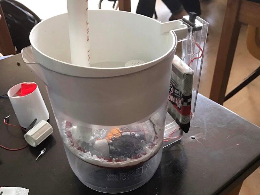
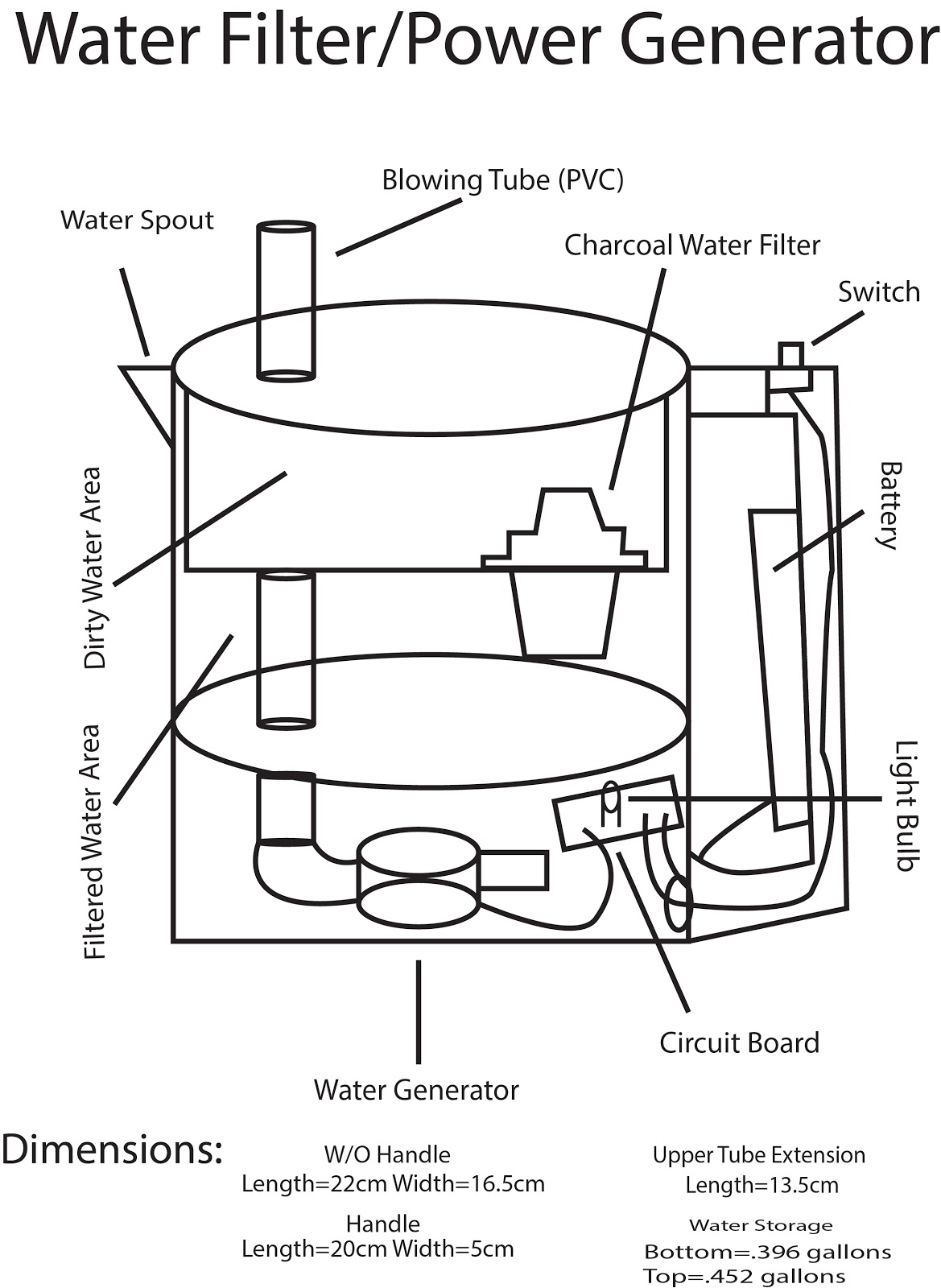
Our project consists of a Brita filter, modified to accommodate two different sections, one for filtering and one for generating electricity.
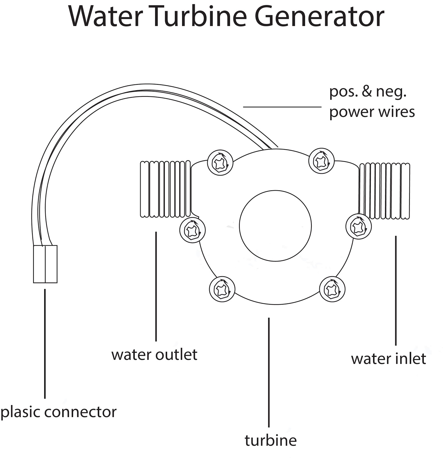
The Turbine and the FilterInitially, our plan was to have the water flow through the filter, and then through the turbine, in order to streamline the process as much as possible. However, this became challenging because the water pressure leaving the filter was far too low to power the turbine.
To remedy this, we decided to make the lid of the pitcher slightly smaller than the exact dimensions of the pitchers, and coat the insides of the first chamber with rubber, so that the lid could act as a plunger, pushing the water down, pressurizing it, and forcing it through the filter and the turbine.
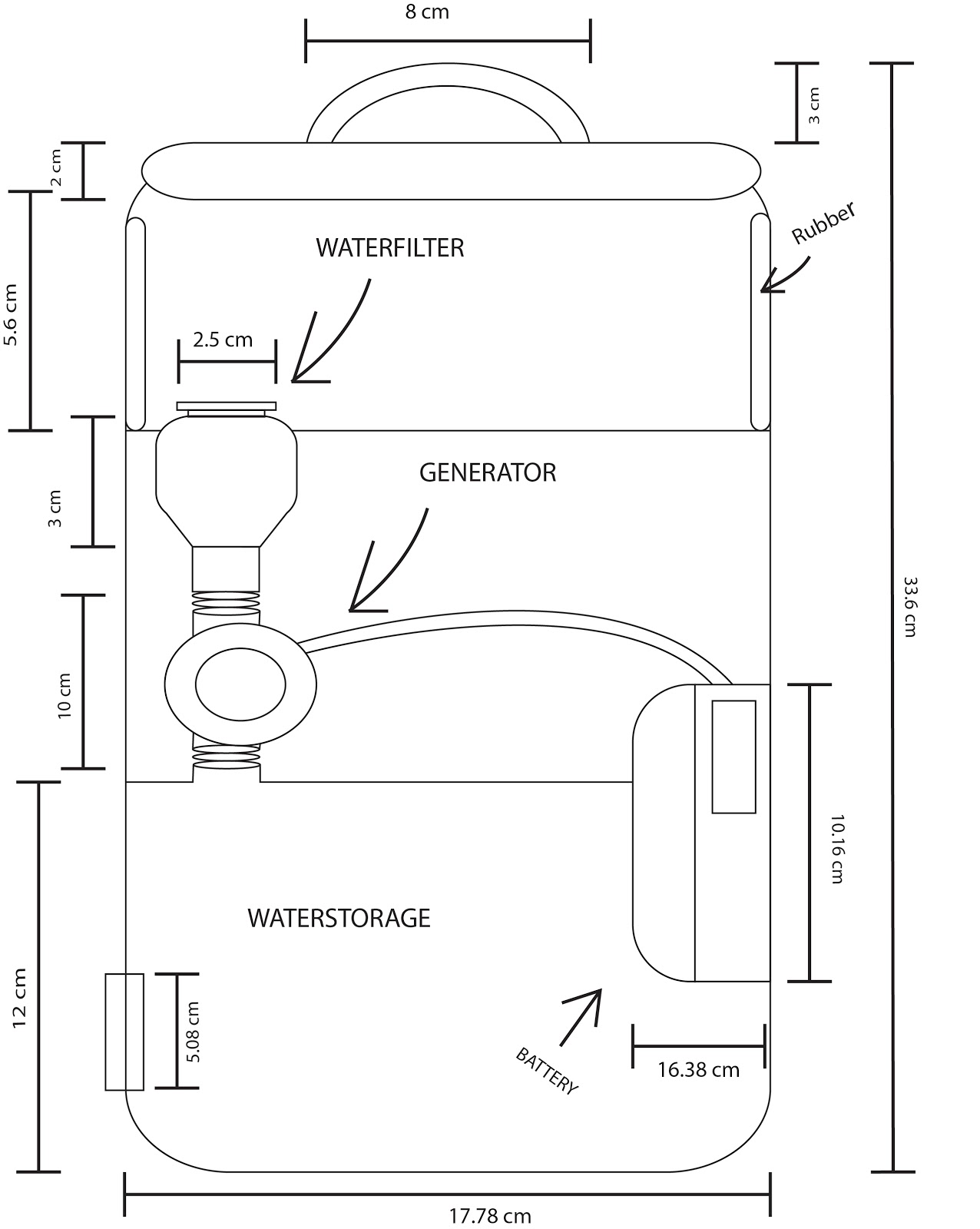
Our original mock-up looked like this:
However, we learned that we did not have the resources or budget to rubberize the sides of our pitcher.
Then we tried to reorganize the setup so that the water could flow into the turbine and then into the filter. This became difficult because the filter input had a larger area than the turbine output, so water would simply spill out and not all end up in the filter.
On accident, we discovered that blowing into the turbine could cause it to spin as well. We felt this was a sufficient solution to the configuration problems we were having. Thus, we then attached a long tube to the input of the turbine and organized it so that the user could simply blow into the device.
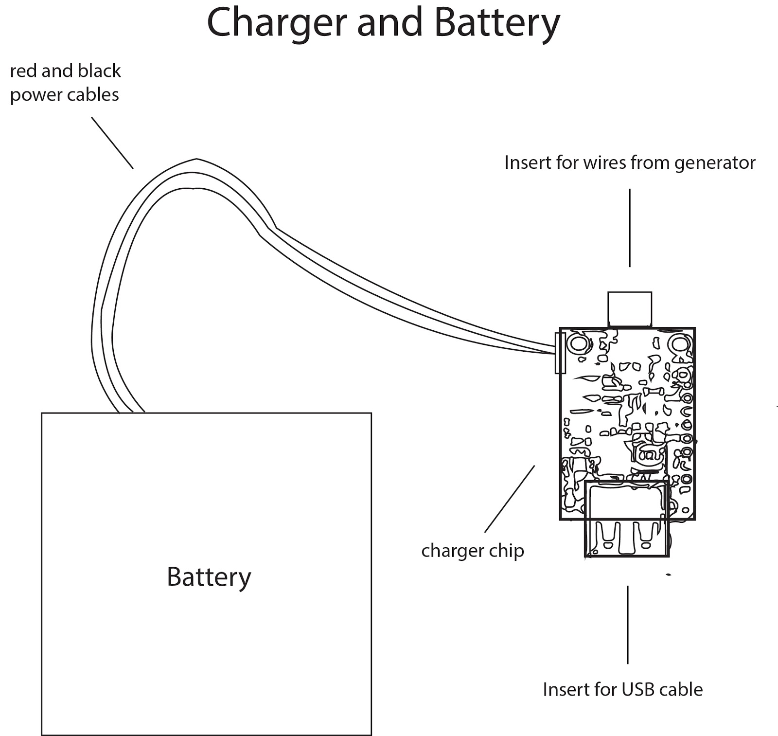
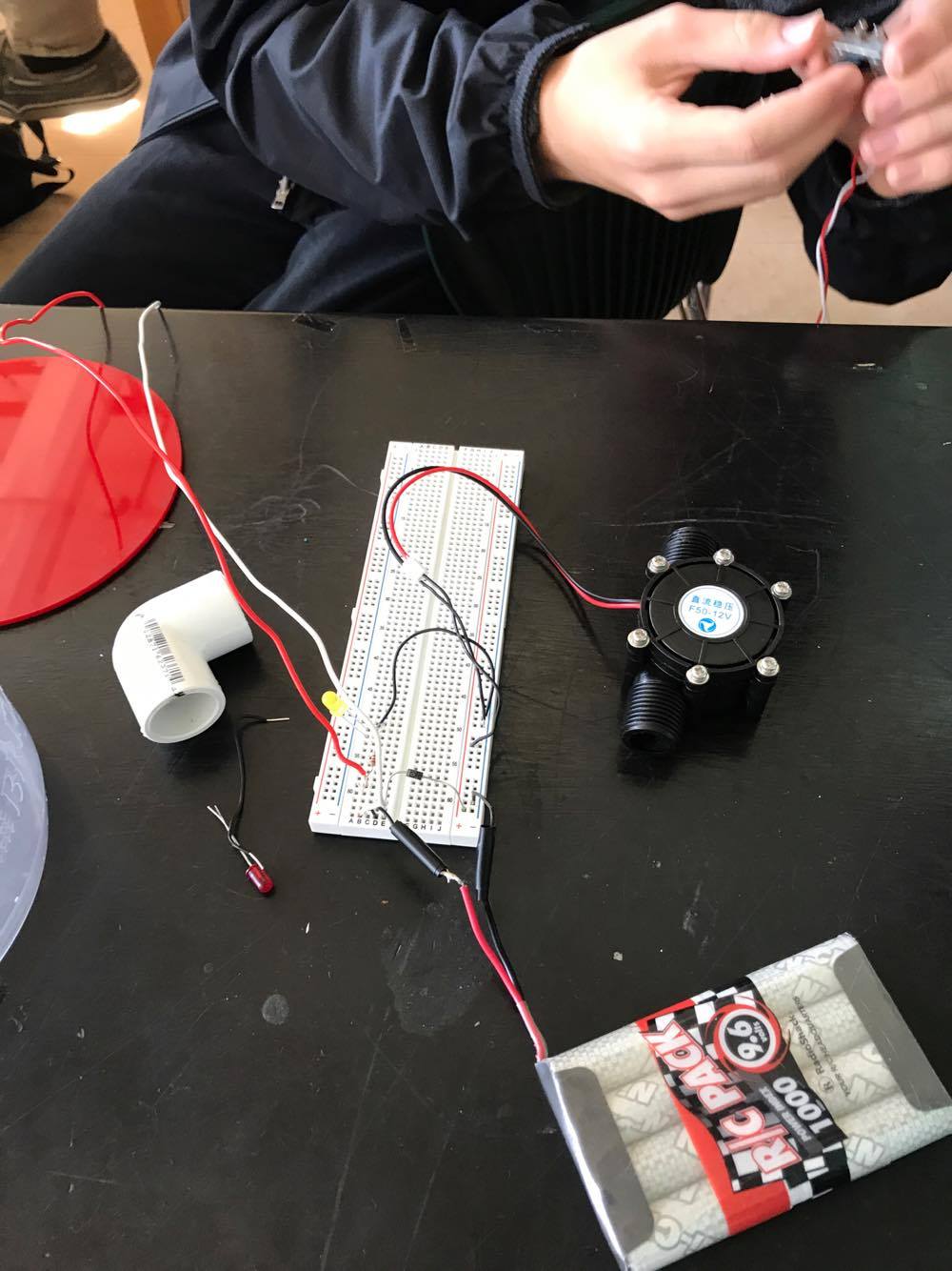
Our final mock-up design looked like this:We felt it would be most convenient for our target client if they were able to have not only a supply of electricity, but also an onboard LED that could be toggled via an onboard switch. We also decided to put the switch and the battery into the handle of the device to maximize the usage of our space, since the pitcher is not fairly small to house all of the parts required. Schematics of our wiring can be found in the attachments.
Laser Cutting and ConstructionThe exact radius and circumference of the divider that you need depends on the dimensions of your pipe. Our blowing pipe was an inch in diameter, and our pitcher was 5.2 inches in diameter, so this is what we cut. It's important to measure the dimensions of the inside of the pitcher exactly where you want the divider to go. Some pitches curve slightly inward as they go down, which will limit how far down your divider will go if you're not careful.
A schematic for the laser cut divider can be found in the attachments.
Additionally, we made our blowing pipe approximately 1.5 feet in length using the hacksaw, enough for it to stick out slightly from the top of the pitcher for blowing. However, this might need to be adjusted proportionally for your pitcher.
Additionally, two holes need to be drilled in the side of the pitcher near the bottom part of the handle for the battery and switch wires to come out. Any small drill should do the job.
Once you are sure EVERYTHING inside the bottom compartment is how you want it, then you can caulk around the edges of the divider. This is permanent!
NotesAlthough we didn't get to build our original design with the plunger lid, our blowing tube design was functional and effective. However, if anyone is interested in building the plunger design, it would most likely require the same parts listed here (plus the rubber and additional divider). I would love to see how it goes!






Comments
Please log in or sign up to comment.