I created this project for a couple of reasons; one, I got tired of trying to get the built in garage door openers in my vehicles to work with both of my garage doors. Second, was that nagging question "Did I close the garage door?". Now I can get that question answered with a couple of taps on my smart phone. Also, the device will send me an openHAB notification to my smart phone if the garage door is left in the "AJAR" or "OPEN" position for longer than 15 minutes.
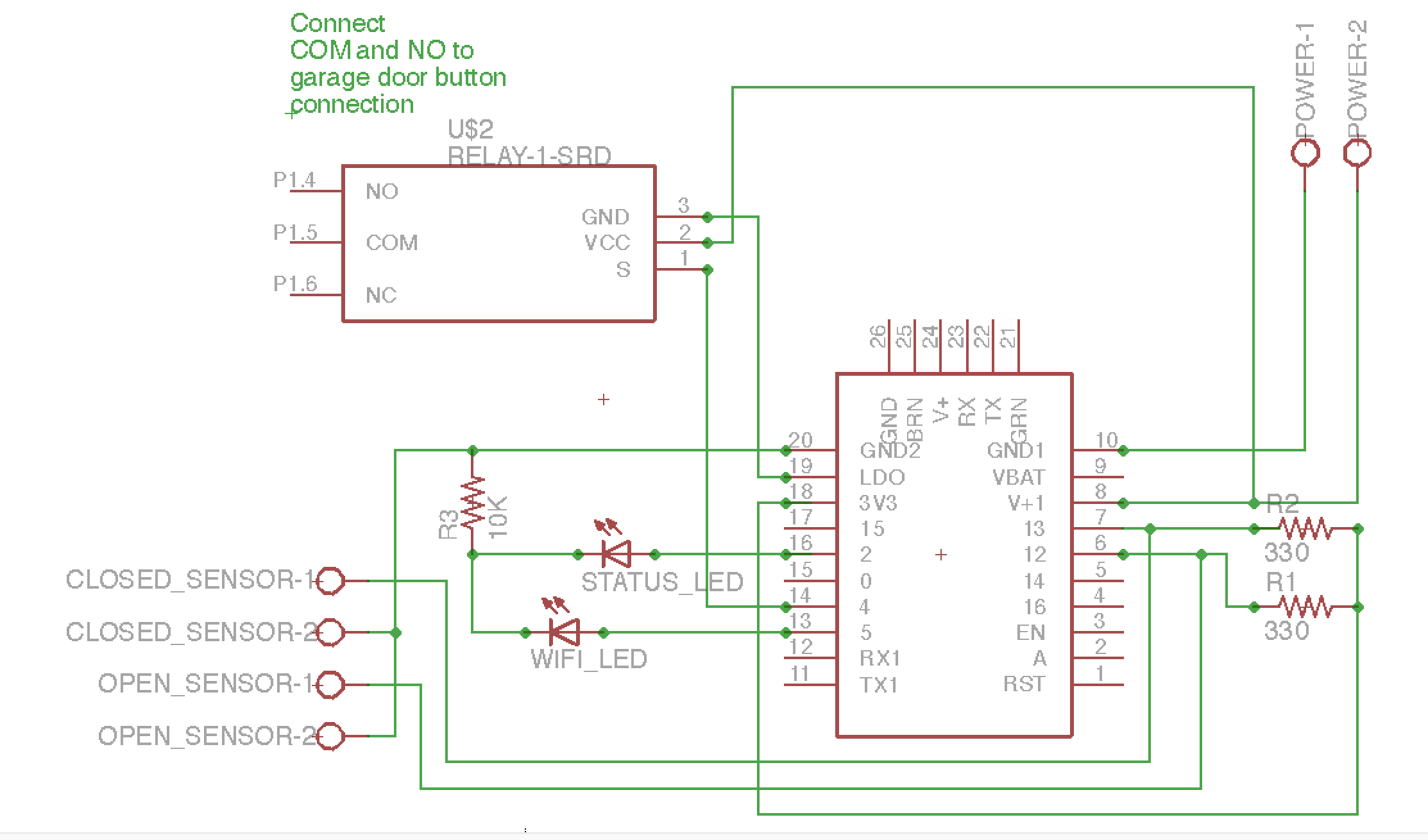
The project consists of a HUZZAH, relay, power supply, resistors and LEDS. The HUZZAH connects to your local WIFI and runs a small web server that responds to simple http GET/POST requests that will be sent to it via openHAB. The relay works just like your existing wired garage door switch to activate the opener except for it's controlled over WIFI via the HUZZAH. The LEDs are there to provide you status information. The red LED flashes if the garage door is not in the open or closed positions. The yellow LED flashes constantly until connection to the WIFI is established. It will also flash briefly every time a valid request is sent to the web server.
In this writeup I will cover building and installing the garage door opener project. I will not cover installing and configuring openHAB, there are plenty of articles on the web that cover that. However, I do provide sample open HAB configuration files for the project.
Steps:
- Download and install the Arduino IDE 1.6.5. NOTE: Don't use the latest 1.6.7. I've have had problems getting the project to compile with the ESP8266 libraries when using 1.6.7.
- Install header pins on the Adafruit HUZZAH. Directions can be found on the Adafruit site at:
https://learn.adafruit.com/adafruit-huzzah-esp8266-breakout/assembly
- Setup Arduino IDE to support the Adafruit HUZZAH. Directions can be found on the Adafruit site at:
https://learn.adafruit.com/adafruit-huzzah-esp8266-breakout/using-arduino-ide
- Download the "GarageDoor 8266 Controller Code" and save it as "GarageDoor.ino" and open it in the Arduino IDE. Make sure you set your board type to "adafruit HUZZAH ESP8266" and try to compile it. If it fails with an error about unable to find ESP8266WiFi.h. Edit the sketch and remove the first two lines #include <ESP8266WiFi.h> and #include <ESP8266WebServer.h>. Next from the Arduino menu select "Sketch->Include Library" and scroll to the bottom under "Contributed libraries" and add them both back in. When you do so it will add four more libraries than just those two libraries. Save and compile the sketch again and it should work. You can delete all the extra included libraries once you have it compiling.
- Build the garage door opener circuit on a bread board and upload the sketch to the HUZZAH. This will give you a chance to understand and test the project before you solder up the final project. To test the project I use Postman www.getpostman.com a google chrome plugin. With Postman you can send a http GET and POST requests to test that everything is working correctly. To test the relay, send a http POST "http://YOUR_DEVICE_IP_ADDRESS/device/activate". You should hear the relay click, see the LED on the relay flash on and off and get an "OK" in the body of the http response . To test the open and close contact switches send a http GET "http://YOUR_DEVICE_IP_ADDRESS/device/status". You should get an "OPEN", "CLOSED or "AJAR" in the body of the http response. The response you get depends on which contact switch sensor you place the magnet half near.
- Build the garage door opener circuit on a PCB board. Started by hot gluing the relay down to the PCB in the upper left corner and then add the HUZZAH by soldering one or two pins to the PCB to hold it in place.
- Add the LEDs they need to placed as shown to match up with the 3D printed case design provided. Install them so the bottom of the LED is about an 1/8 of an inch above relay. That way they will fit neatly in the holes in the case lid.
- After the LEDs add all other components and solder them in place with the connections shown in the images. To make the circuit connections use small pieces of stripped CAT-5 cable wire. I find trying to make the solder flow from one solder point to another just leads to large blobs of solder. I also used an old computer CD audio cable to connect the relay.
- Before installing the device on your garage door you should get openHAB up and running. Test all the functions of the device thru openHAB before installing. NOTE: if you want openHAB to send you notifications like the one in the rules file you must use openHAB 1.8 or newer.
- Install the open and close contact switches. If you have a Craftsman or Chamberlain screw drive garage door opener you can use the 3D printed mount designs provided. I suggest using hot glue for all the glueing. Hot glue dries fast and can easily be removed if you need to reposition the mounts or contact switches. Start by gluing one of the contact switch magnets on the the trolley. Slide both mounts onto the track from the motor end. Close the garage door and position a mount above the trolley. Glue one of the contact switches on the mount with no more than an 1/8 gap between the switch and the magnet on the trolley. Use a multimeter to measure the resistance across the switch leads to verify that it reads closed. Hot glue the mount in place on the rail using a small amount of glue. It's my experience that the magnet and the switch need to be slightly offset for the switch to read closed as seen in the images. Open the garage door all the way open and repeat the process. Run wire from the contact switches to the back of the motor using cable tie mounts to keep wire from getting tangle in the trolley.
- Connect 2 pieces of wire about a foot long to run from door control connections on the opener and back to the relay. Connect them to the door control connections as described in your owners manual as if you were installing a switch. To see if you have the correct connections simply short the two wires together and the garage door opener should activate.
A few screen shots of openHAB on my iPhone.
Future enhancements
- Add some security. I plan to do something between the openHAB rules and the sketch passing a constantly changing token between the two. If the tokens don't match up the device won't open the door. Until then I'm not to worried because to access the device you have to be connected to the local network which is password protected. Remote access is provided and secured via openHAB. I feel it's probably easier to just break a window than to hack the WiFiI network and figure out how to activate the garage door.
- Look at using the Adafruit HUZZAH feather. The first version of this project was built using just a ESP8266-12. But by the time I added a buck converter, reset and flash buttons the cost was a lot more then then HUZZAH. It looks like uploading code to the feather is easier than the HUZZAH and I can use a standard USB cable to power the device.


Comments
Please log in or sign up to comment.