


Hardware components | ||||||
| × | 1 | ||||
 |
| × | 8 | |||
| × | 1 | ||||
| × | 1 | ||||
This Guide is part of my upcoming book Prototyping with Lego, M5Stack and UIFLow Expected December 2022.
In this guide I will show you how to use the PCA9554PW Ext I/O unit from M5 Stack.
As with serval of my later project published on Hackster.io I will be use the Core2 AWS (yellow) as my controller and mounter in a custom lego test frame.
The Lego test Frame.I have created an instruction PDF for the frame here if you wish to have a downloadable copy of the following instructions. You can find the download here.
The lego test frame is made using two 19X11 stud technic plates ins Medium Azure. Finding cheap (official) sets that contain this part is difficult and so I had to order them using this link (not sponsored or affiliated!)
Two 5X7 Beam Frames in Medium Stone Grey (I don't have them in Azure)
And eight black Technic Friction Pegs.
First step is to lay one of the 11X19 Technic plates onto a flat surface.
Next step is to insert 4 friction pegs.
Step 3 is to add the side beams.
In Step 4 we turn the assembly around and add the friction pins that will support the back plate.
In Step 5 we add the back 11X19 Plate
In Step 6 We add the friction pins that will hold the M5Stack Core2 and EXT I/O
And that's all the Lego Technic parts assembled.
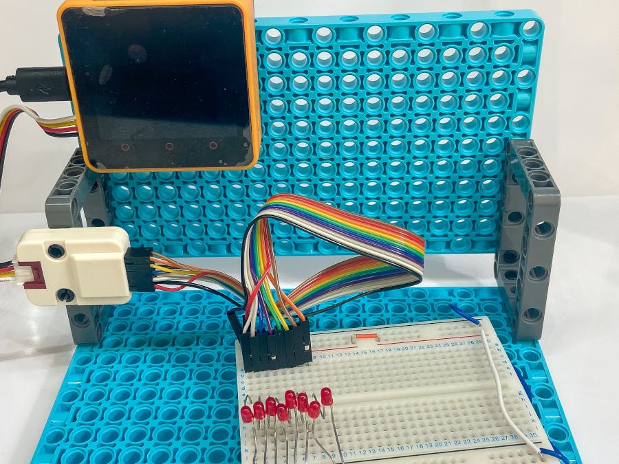
The Core2 AWS in placed on to the four pegs on the back panel and the EXT I/O is place on the side Beams. Alas, 3D parts don't exist in Studio for the Core2 and EXT I/O and so you will have to make do with a photo.
Here I have connected the grove lead between the Core2 and the EXT I/O and connected the EXT I/O to a breadboard with jumpers and LEDs. for a basic test example.
Using the pins as Outputs to light LEDS.In UIFlow add the EXT I/O by clicking the + under the Core2 image, select the core two and then click OK.
We can see that UIFlow has now made the EXT I/O code blocks available to us to use in our programs.
If we select the first block, set the mode to ALL_Output and run the program, all LEDS will light up!
To make the LED's turn off and on we need to set the pin status to low and then high. For this we use the Digital Write Pin block.
With this block we can control one of the 8 pins and set it to high (on 3.3v) or low (off 0v).
The following code sets each pin low to turn off and and then high to turn on in a cycling pattern.
You can see a video of the code running below.
As you can see in the video, the LED sequence is in reverse. This is not an error but to do with the hardware or more specifically the PCA9554PW chips I/O pins. Normally the I/O pins would be in order of 0 to 7 Lowest bit to heights bit but on the chip, the pins start at 7 and go down to 0.
This matches with the arrangement shown in the Datasheets register table
Knowing the pin arrangement and how it relates to the table is important when it come to using the Digital Write Hex Value block.
The Digital Write value block uses Hexadecimal values which are translated into binary inside the chip to address the pins. In order to control the individual pins using this block you will need to have knowledge of how Hexadecimal is translated to Binary. When working out the values I tend to use the converter found on the Rapid Tables Web Site.
Using the EXT I/O for Inputs.
From what I can tell from the data sheet, When the pins are set as inputs the pins can only be high or low and unable to read voltages between these states (the pins are digital and not analog.)
To read an individual pin we use the read pin block.
As this block only returns a value, we need to use it with additional blocks for example.
If the pin is left open or floating, the block will return a 1 but if the pin is pulled to ground, the block will report a 0.
If we replace the Digital Read Pin block with a Digital Read port block,
And run the modified example:
The value will be returned as a decimal value.


Comments
Please log in or sign up to comment.