


Hardware components | ||||||
 |
| × | 1 | |||
 |
| × | 1 | |||
| × | 1 | ||||
| × | 1 | ||||
| × | 1 | ||||
| × | 1 | ||||
Software apps and online services | ||||||
| ||||||
Part 1- Electronics
In this first part of this series I will show you how to control a OO/HO locomotive on a simple loop of track using the Following M5Stack products.
- Fader Unit
- GoPlus2
- Core2
- Parkside Team X12V battery
- Loop of track
- Locomotive
- Peco Powerfeed Joiners
The first thing we need to do when assembling the electronics is too remove the screws in the Base of the Core2. Once these are removed we can extract the expansion PCB and detach the baseplate. Warning: the battery is stuck to the baseplate and will need to be removedcarefully.
Now place the Goplus2 into the back of the Core2, insert the battery into the baseplate and replace the baseplate.
The fader Unit uses a sliding 10K Variable resistor similar to the angle units 10K rotary variable resistor but where the Angle unit uses a resistor divider to reduce the voltage from 5V to 3.3 volts, the Fader Units has a DC>DC converter to reduce the 5V to 3.3V. The variable resistor also has a detent in the body so that there is a light "Stop" point in the middle. The Fader Unit also comes with 14 RGB LED's in two rows that with some careful programming, we could use as a visual indicator of the variable resistors position of as a speed/volume indicator.
The Fader unit needs to be connected to Port A (Red Port)
.
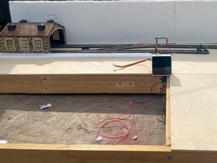
Next we need to prepare the connection from the Goplus2 to the track. The Goplus2 has two motor out connections that we can use to drive two separate loops or one locomotive and another motor in scenery. The Goplus2 comes with two connectors for the motor in the pack but if you need replacements they are XH2.0 2P connectors.
The length of wire on these connectors is short and will need them to be soldered so that the Core2 is very close to the track. If we want to put scenery on the baseboard, we need to extend the wires.
To extend the wires we will need:
- XH2.0-2P connector
- Red Silicone coated Wire
- Black Silicone coated Wire
- Heatshrink tube
- Solder
- Soldering Iron
- Peco Powerfeed Joiners
The Loop of Track
Now we need to assemble the loop of track and fix it to the baseboard.
Here I have two loops and an internal siding which will be the start of my new layout. I am using Peco Powered Rail joiners to connect wires to the track in order to avoid using Hornby's big ugly power connectors and because I have never managed to solder successfully to fishplates or track.
Part 2 - PowerSupply
The whole layout will be powered with Parkside Team X12 batteries in order to keep the layout mobile. I chose the Parkside Team X12 system as I have quite a collection of the Team X12 tools and batteries are normally easy enough to find but if not then 12V packs are easy enough to connect instead.
In order to mount the batteries to the baseboard I needed to 3D print an adapter out of PLA. Thankfully Thingiverse member Glol has taken the time to model the adapters and so I am providing a link to his thingiverse page: https://www.thingiverse.com/thing:4445077
I don't have the exact connectors GLoL used but but I have some think connectors that I used in place. The Battery mount is screwed to the side of the baseboard and connected with a barrel jack which plugs directly into the Goplus2 module. This isn't ideal and really should have a fuse fitted in order to protect the Core2 and GoPlus2 module.
Part 3 - The Test program.Once everything is connected I ran the following test code:
And find my first problem, my old loco was making some squeaking noises but not running. Using a test meter I checked the voltage from the battery which came out as 12.31V as as seen in the earlier video is enough to directly run loco. My next step was to check the voltage output from the GoPlus2's motor port and found its maxing out at 2.5V !
After back tracking and searching various documents I found these pins are directly connected to the STM32 F03 which only has a PWM output voltage driver of 2.5V, not nearly enough for a 00 Gauge loco.
After two days of tinkering and playing I changed my test code to just test the motor output. After a lot of digging I found the the values for the motor outputs are -127 to 127 which gives an output voltage of -5V to +5V. The loco still wouldn't, I gave the track a quick clean with my fingers and its working!


Comments
Please log in or sign up to comment.