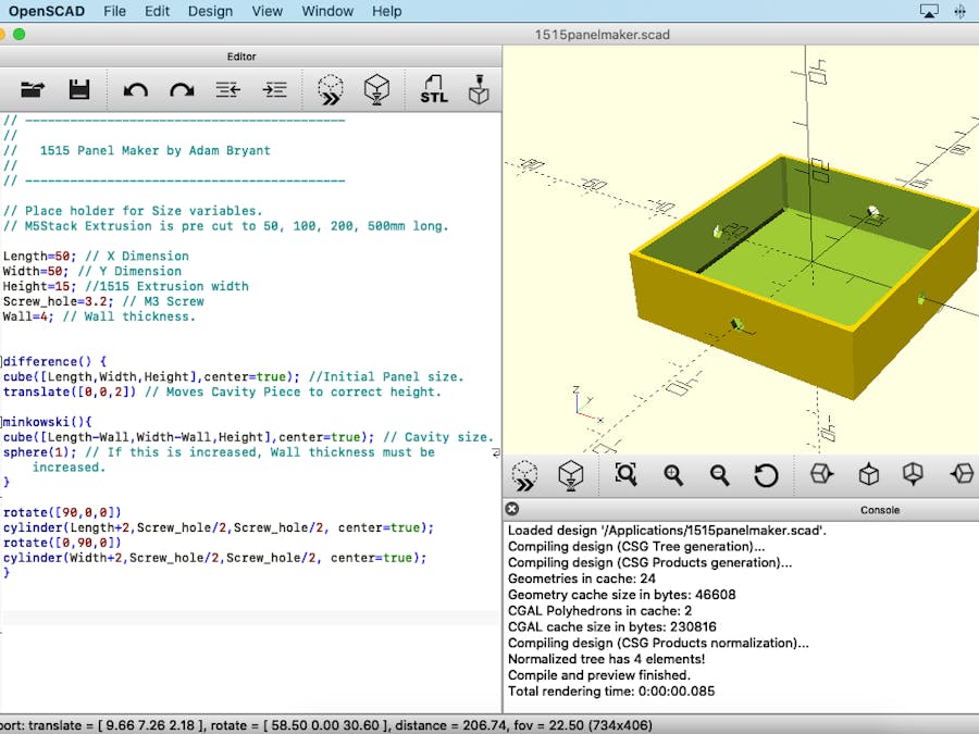
I originally created the Panel maker in Fusion 360 (not sponsored) and some member of the M5Stack community complained about having to install the program. Not sure what to do, I looked for open source cad programs and came across OpenSCAD https://openscad.org.
After downloading and installing OpenSCAD, I opened up the program and was utterly confused.
I didn't know that a mathematical programming language was used to make things and spend ages looking for drawing functions like in F360. After bit of reading I worked out how to get started.
M5Stack aluminium is 1515 V-slot which means it is 15mm X 15mm with a V profile channel.
And is available in pre cuts lengths of 50, 100, 200, 500 and 1000mm long.
The Extrusion is connected using a range of Plastic parts made just for the profile and also available from M5Stack. The Plastic connectors use M4 countersunk screws which screw into the pre tapped ends while the slide nuts use smaller M3 Screws.
When connected together, the Plastic add 30mm to the overall external size of constructions but, leaves the internal spaces as 50, 100, 200, 500 and 1000mm's. With this data I was able to make a start on creating the code and so I first started by adding the dimensions as variables to OpenSCAD.
Now I had my basic dimension I could start creating my first shape. I started by creating a box of 50X50X15mm.
The code for the first shape is:
cube([50,50,15],center=true); //Initial Panel size.If I tried to change this using the variable I had written above I would have to manually change the numbers which would cause me problem in the following steps. After a bit more reading I discovered I just needed to change the line to the following code which you see in the screenshot above.
cube([Length,Width,Height],center=true); //Initial Panel size.After saving this line of code nothing happens. to get the preview to appear I need to click on the icon of a cube with two arrows and the first shape appears!
Now I had the main dimension of the panel defined, I moved on to hollow out the panel. Unlike F360, there is no shell command and so we have to create another object that will be used to subtract the internal space from the panel.
For this I needed another Variable I called Wall.
Wall=2; // Wall thickness.The Wall variable is used to reduce the size of the inner shape that will be used to make the cavity. The code for the new shape is almost the same as the first but we add -Wall to the dimensions.
cube([Length-Wall,Width-Wall,Height],center=true); // Cavity size.When the new object is subtracted for the old object, setting wall thickness to 2 gives us a final wall thickness of 1mm on each side.
After we type in the new code and hit the icon again, the new shape will be drawn but we don't see it because it is drawn inside the old shape.
In order to make the second cube visible we need to translate the cube up 2mm. To do that we use the following code:
translate([0,0,2]) // Moves Cavity Piece to correct height.This must be placed before the second cube or both cubes will be moved.
In order to create the cavity by subtracting the smaller cube we use the difference() {} command. The cubes must be wrapped in the difference command in the correct order otherwise the wrong cube will be subtracted.
difference(){
cube([Length,Width,Height],center=true); //Initial Panel size.
translate([0,0,2]) // Moves Cavity Piece to correct height.
cube([Length-Wall,Width-Wall,Height],center=true); // Cavity size.
}
Fortunately for me I have them in the correct order and so when I use the difference command the panel will have the hole in the correct place.
The next step is to add holes in the sides for securing the panel to the aluminium using the slide nuts. This is done with the cylinder command:
cylinder(0,0,0, center=true);The dimensions here are length, radius end 1, radius end 2. This got me a bit confused because fusion only has lengthX diameter. In order to get the cylinder size I needed I had to type:
cylinder(Length+2,Screw_hole/2,Screw_hole/2, center=true);Length needed to have 2mm added to the end otherwise it wouldn't punch trough and Screw hole had to be decided by 2 because my variable was for diameter and not radius.
After rendering I found my hole in the wrong place. To move it to the correct place I needed to rotate the cylinder using the rotate command
rotate([0,0,0])Rotate's values are X axis, Y axis and Z axis and so to rotate the cylinder I use:
rotate([90,0,0])Next we repeat the cylinder but rotate around the Y axis instead of the X axis.
At this stage we could call this complete and print the model but, from experience I knew the sheer internal side would cause me issues. To solve this I needed to add a filet but unlike F360, this is no easy task. After a lot of googling I found I needed to use the minkowski(){} command. For the Minkowski to work we need to define a sphere whit it will trace around the edges of the internal box to give the edges a fillet.
First we define a sphere of 1mm:
And then we wrap the internal box in the Minkowski command and discover that we loose a wall:
To fix this error caused by the Minkowski command all we need to do is change the Variable Wall from 2 to 4.
And we now have the completed panel. Save the file but before we can create the.stl click on the icon with the egg timer to make a final render.
The image doesn't look any different but the console will show data about the finished file. Click on the stl icon to export the finished file, Convert the stl into G-Code using the slicing program of choice and then print the finished panel.
In order to rescale the panels you just change the variable values, re render and re-export and done.


Comments
Please log in or sign up to comment.