

Hardware components | ||||||
| × | 1 | ||||
| × | 1 | ||||
 |
| × | 1 | |||
| × | 1 | ||||
Software apps and online services | ||||||
| ||||||
In this project we will use the M5Stack K-Meter and SSR to control a PTC heater module for SMD component heating.
For this you will need the following components:
- 6 X 1515 Aluminium Extrusion 100mm Long
- 10 X 1515 Aluminium Extrusion 200mm Long
- 8 X Corner Brackets
- 32 X M4 10mm long Countersunk Screws
- 4 Slide nut
- 4 X M3 15mm Brass Standoffs
- 4 X M3 6mm Countersunk Screws
- M5Stack SSR Unit
- M5Stack K_Meter
- Core2
Take 1 X 1515 Aluminium Extrusion 100mm Long, fit the corner brackets with M4 10mm long Countersunk Screws.
Next take 2 X 1515 Aluminium Extrusion 200mm Long and fit to the corner brackets with M4 10mm long Countersunk Screws.
Repeat 3 More times until you have four "U Shapes.
Take two of the "U" shapes and connected them to the other two using M4 10mm long Countersunk Screws so that you end up with two constructions like in the following image.
Put these two parts to one side as its time to build the heat plate mount.
Take the four 15mm brass standoffs and attach to the heat plate using four M3 6mm countersunk screws, do not tighten up.
Fit a slide nut to each of the four brass standoffs but do not tighten up and the screw end may be too long.
Slide the remaining two 1515 200mm long Aluminium Extrusions onto the slide nuts.
Fit M4 10mm long Countersunk Screws into the ends of the two 1515 200mm long Aluminium Extrusions
Slide the remaining two 1515 100mm long Aluminium Extrusions onto the ends of the 200mm 1515 200mm long Aluminium Extrusions.
Fit M4 10mm long Countersunk Screws into the ends of the two 1515 100mm long Aluminium Extrusions.
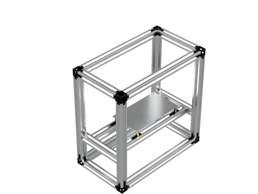
Slide the Hot plate assembly onto one of the frame sections as show,
Slide the other part of the frame assembly over the first part as shown, the Bed assembly should be secured 50mm above the bottom of the frame so that a 50X100 panel can be fit in place below. And that is the hardware assembly complete.
Warning, this hotplate uses 220-240V AC. do not attempt to use it if you have no experience working with these voltages!
The K-Type thermocouple is attached to the bottom of the heatplate using Kapton tape before being plugged into the K-Meter.
The K-Meter is connected to the Core2's Port A (Red Port).
The SSR is connected to Port B (Black Port) via a T-Unit that allows an angle sensor to also be connected to the same port.
Programming the Heat chamber.The Following is just a basic code example.
Unfortunately when activated the heat plate starts to warm up and then immediately stops working. It took me while to work out why but inside the SSR is a 2A fuse.
When first powered, the heat plate has a low resistance of around 600 Ohms which causes the heat plate to draw around 5Amps before dropping do to around 1.6Amps.
I was not aware of this as documentation is hard to find and ended up blowing 2 fuses before finding this out. This initial surge allows the plate to heat up to around 200 degrees really fast but for SMD soldering, we need to slow that down and for this we need to make some kind of "Soft Start" to protect the fuse and slow down the heating process.
Soft Start Controller.
While there are lots of diagrams on building soft start controllers, they theory and calculations are hard to discover and commenters on the above video said that I need add a resistor inline to reduce the start up serge however, no one was able to tell me how to work this out or what size of resistor (in both value and power size.)

Comments