Locks protect our buildings, our homes. There are good locks, bad locks, but a quite common thing is that they usually have a keyhole that anyone can easily access. Robbers often exploit this when they break into your house. Picking a lock is an art among them. I want to help you with this issue by removing the keyhole from your door!
There are locks that solve this problem, but they usually have other security issues.
RFID-based locks have an obvious interface to access the locking mechanism: the card readers. Entering codes using numeric keypads might seem safe but there are numerous ways how robbers can break into buildings with these numeric keypads. Even your phone could be a wireless key, but if its battery dies or your phone breaks, you can't even enter your own house, so you'll still need at least a backup key.
Keyless locks usually lack the safety and/or they are quite expensive.
My ideaI wanted to create a simple, cheap and cool way to unlock doors in my home by using magnets!
The basic idea is to rotate a magnet in a sequence, while the 'keyhole' - my locking circuit - is behind your door. It means that there's no external access to it. The sequence itself is your key so you can open any door of the building if you know the code. It is similar to how you open old school safes, but without an obvious locking mechanism.
The 'keyhole' can be anywhere on the back of your door without any obvious indicator from outside. If you want, you can even easily move it from another place without any issue. If it is confusing, here's a video about how my magnet lock works during testing:
HardwareTo create this project, I used the Infineon Magnetic Sensor 2Go (MS2GO) board, equipped with a great onboard 3D magnetic sensor, the TLE493D-A2B6 as it seemed to be an obvious choice. It has everything I needed besides the solenoid driver - TIP120 - and it is very easy to use.
Electric locks often use solenoids to temporarily unlock doors so I also used a simple solenoid to do this. My solenoid should be powered with a 12V power supply so I used one of my old 3S LiPo battery for testing, but you can use any 12V power supply.
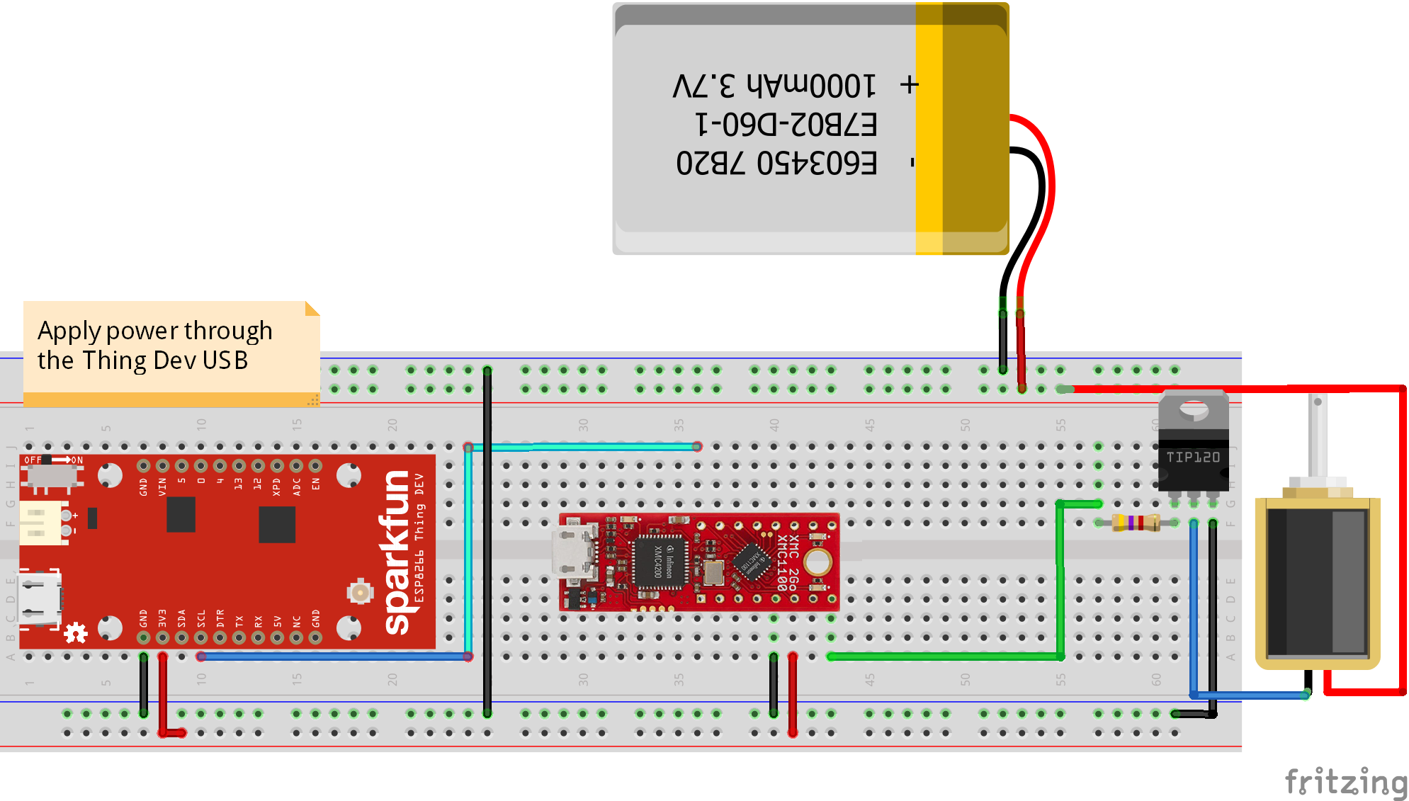
The MS2GO kit has a couple of GPIOs, but for this project I only needed one. It is used to control a TIP120 transistor that can power up the electromagnet of the solenoid. It is a pretty simple setup:
At the moment the MS2GO is powered from USB and the solenoid is powered from a battery. With some extra hardware you can easily use just one power supply for the whole project.
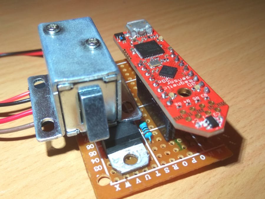
I built the circuit on a proto PCB:
During development I used the rotatory knob that I got in the package, but later on I moved on to use a custom magnet key.
My magnet key is nothing special, two bottle caps glued together with a strong magnet inside. I also added numbers on the top. It will be used to set the code when I open the door.
SoftwarePrograms for the MS2GO can be developed in a couple of ways, including Arduino IDE. I went on with Arduino IDE because it is very easy and fast to develop anything with it. If you also want to use Arduino IDE to program the XMC microcontroller boards (e.g. the MS2GO board) from Infineon, follow the description at their github repo. You will need one more thing: a library for the sensor.
My system will be in idle mode until a there's no nearby magnet. After it detects a strong enough magnetic field, it will calculate the rotation of the magnet and decode it to the 1-8 value on the bottle cap. If you want you can use 0-9 or other values too, but I liked the 8 segment bottle cap. The key code can be as long as you want, but for demonstrating purposes, I used a 4 number long code.
The status of the built-in LED and the solenoid will change together. I use the LED for feedback purposes. Once you enter the correct number sequence, the lock will be unlocked for 10 seconds. Of course if you want more or less time, you can change it easily.
The sensor seems to be very accurate. I was surprised that it was very easy to accurately detect small changes of the magnet's position and rotation. Everything just works, no magic needed.
The only slightly difficult thing was preventing the code from bouncing from one number to another back and forth at the borders. However this is nothing new when we are working with analog signals. The fact that the data can 'overflow' due to how the rotator knob and the sensors works required me to do some extra coding.
The entered code handled in a FIFO way, meaning that you don't have to reset the code or anything like that between entering two codes.
TestAs currently none of my doors support electric opening, I had to build a demo setup to show how the hidden magnetic door locking works.
I glued everything to the back of some plywood. The sensor faces towards the plywood. From the other side you can see nothing, but if you know where to look and the combination, you can easily unlock the door using the solenoid:
You really have to know what you are looking for if you want to open a door with this lock.
ConclusionThe system works extremely well. I believe that the hidden design is a big win. Even if you lose your 'keys', all you have to do to open any door in the building is to find a good magnet and remember the code. These locks would be a very useful part of smart buildings or smart homes.
The Magnetic Sensor 2 Go board is very compact and easy to use. The 3D magnetic sensor is great! I expected more problems with a magnetic sensor but it provided a good, reliable and easy way to process data.
To talk about the future: as an improvement, I'm thinking of creating a simple electromagnet array from old BLDC motors to simulate the rotations of the code. That way you just put the key to the correct place to open the door, but if you lose the key, you can use the good old rotating magnet technique, too. I feel that there is potential here.
Thank you for reading and have a nice day! As an extra content, here's a geeky red panda from work:
In the meantime I created a new project, Home Manager. During that project I partially continued this project, too. In its previous state it was a simple, offline device. In the new version I gave it a restricted internet access, meaning that I can open the lock remotely with my Home Manager device.
The connected network for the Home Manager is based on MQTT messages. If you are unfamiliar with MQTT messages then please take a look at this page. Anyway, this image might help you understand MQTT, it is very easy:
Based on this knowledge, I connected an ESP8266 to the Sensor 2Go. The ESP8266 is subscribed to the 'my_door_lock' topic so whenever the Home Manager published an '1', the ESP will "tell" the Sensor 2Go to open the door.
Here's a video about how it is working in action:
This way, the smart lock became an IoT device, too! If you like this, you might want to check on my Home Manager project, too. It also features a Dalek! Have a nice day!


Comments
Please log in or sign up to comment.