In the past I made a couple of projects that worked great, but could have more use with a remote controller. I could have used just my phone as a remote controller, but as an experiment I built a cool and expandable device to do just that.
The project will cover how I built the hardware and what you'll need to do to reproduce it. I'll also explain how the software works and what functions it does have at the moment.
GoalsOriginally I planned on controlling just some of my devices at home: the magnetic hidden door lock, the LED lights above the kitchen sink, the irrigation system of my mimosa plant, and maybe remotely controlling my robot arm. For these functions the required hardware is a fast, battery-powered microcontroller, a display, an accelerometer, and some buttons.
I realized that this setup is capable of more, so I also added some new features to the list: fall detection with emergency email sending, pedometer, jump counter (similarly to one of my previous projects but this time with a different sensor), a Dalek, and of course a games hub.
In terms of output, I have a couple of 1602 LCD displays. but about a year ago I bought an 0.91" 128x32 I2C OLED display, too. I tested it but never used for anything. Due to the limitations and the size of my LCD displays, I used the OLED display in this project.
The MPU6050 6DoF IMU sensor was an obvious choice (good sensor, cheap, easy to use, etc) for input but I also needed 4 simple push buttons in the project for navigating in the menu and interacting with the functions.
It was more difficult to choose the appropriate microcontroller (MCU). I have a couple of Arduinos, different types of ESP8266s, some other bigger MCU boards and the new guy, MAX32620FTHR made by Maxim Integrated. Probably you are familiar with Arduinos and ESP8266s, so I'll focus on the choosen one: the MAX32620FTHR.
Let's start with the form factor: the MAX32620 has the form of the Adafruit Feather boards, meaning that it is quite small. It is compatible with a bunch of shields made for Feather boards, but it is irrelevant in my project, because I won't use any of those. It also has PMOD ports: PORT 0 and PORT 1. You can access these ports from top or bottom, too. I really like this concept and I used only these ports in my project. These ports allowed me to make a very small device without permanently soldering the parts to the MAX32620 or anything like that.
This MCU board also offers highly configurable battery charging and detailed battery status feedback with its MAX77650 power management integrated circuit (PMIC) and MAX17055 Fuel Gauge.
Another great thing of this board is its multiple UART and I2C ports. It has 4 separate UARTs and 3 I2C or SPI ports! That is something that none of my Arduinos know.
It has Arduino IDE support which is great, but it also has a disadvantage over other popular MCU boards: it doesn't have any wireless capabilities. I had to attach an ESP8266-01 to the MAX32620 to make it connect to the internet. It is a really great device but I think they should add WiFi or at least BLE capabilities to this board.
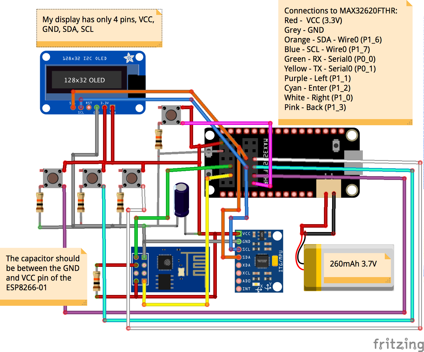
We know all the required parts. All we need is building it! You'll find the schematics at the end of the project. Basically we'll build 2 separate shields for the board and they will connect using the PMOD ports.
Let's begin by removing all the LEDs. The ESP8266 and the MPU6050 has onboard LEDs that we don't need, but they would draw power. Be careful, you should't remove anything else. The MAX32620 doesn't have any permanent on LEDs that we want to get rid of.
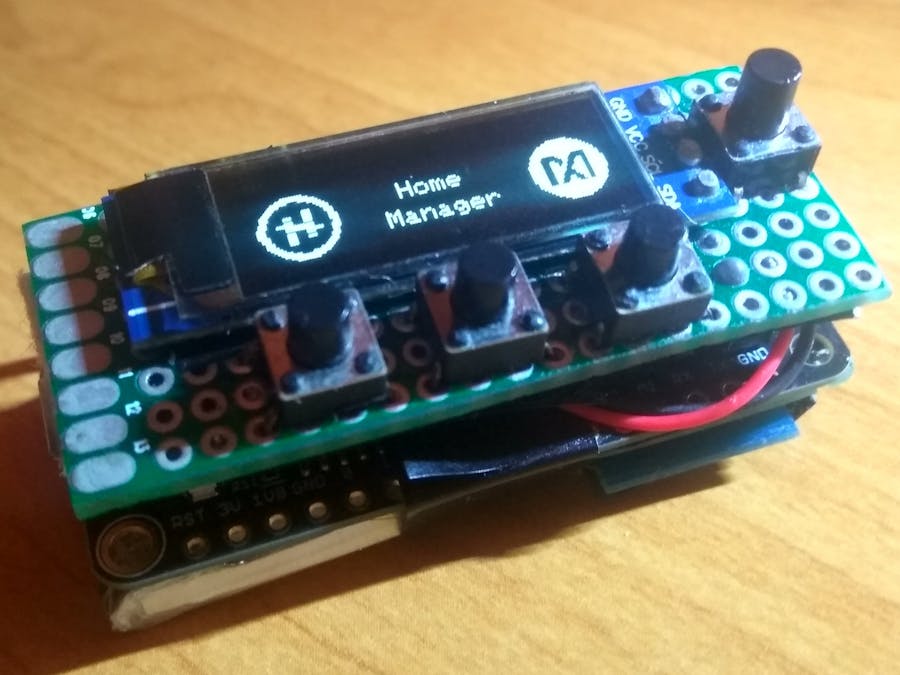
I soldered the OLED display and the buttons into a proto PCB part. I recommend to solder the buttons first then the display later as the display will make it difficult to do the wiring. Trimming the male connectors is a must if you want to make everything fit together. I put insulating tape between each PCB layer (OLED, proto, board, sensor, ESP8266) for precaution. Better safe than sorry. The display shield will be connected to PORT 1. Besides VCC and GND, the display will be connected to SDA (P1_6) and SCL (P1_7) pins. The buttons will use these GPIOs: P1_0 - P1_3. I also soldered a dual cable with micro JST plug to SDA and SCL pins. I'll be using it on the other shield for the IMU. The display shield is ready!
The battery is attached to the bottom of the board. Some double sided and/or insulating tape will make the battery stay in place.
The other shield with the ESP8266-01 (ESP-01 for short) and the IMU will be a lot smaller. It needs to fit next to the battery. I used a 'sandwich' structure here. Firstly I soldered ESP-01 in place with its resistor and capacitor. Keep in mind that it will be difficult (but possible) to reprogram the ESP-01 later, so you should do the programming before you start soldering. You have to connect the ESP's TX port to P0_0 and RX port to P0_1 on the MAX32620. After the ESP-01 is in place you should cover the ESP-01 with the MPU6050. My last sentence might be confusing so please see the images below:
The IMU will almost completely cover the ESP-01. The micro JST cable from the display will be connected to SDA and SCL pins of the MPU6050. As I said earlier, the MAX32620 has 3 I2C ports, so you could easily use another port if you want, but I wanted to use the PMOD ports only. If you need to reprogram the ESP-01, you have to manually put it into flash mode with a cable and then use the PORT 0 pins to access it. It is doable but not very easy.
After this step all you have to do is connect the shields and the battery to the MAX32620 to finish the building!
Wireless communicationThere are multiple ways for how a microcontroller can access the internet using an ESP8266. I choose this method: implementing the application specific communication for the ESP8266 and then make the MAX32620 send app specific commands to the ESP-01 through Serial.
The required libraries can be downloaded from the library manager of the Arduino IDE.
Update the ssid and password to connect to your WiFI network:
const char* ssid = "your ssid";
const char* password = "password of your wifi network";
You can send e-mails, publish MQTT messages to a specific topic and you can also subscribe to specific MQTT topics.
This is the protocol that I made for email sending:
{
 "type":"email",
 "address":"test@example.com",
 "subject":"subject of the message",
 "message":"content of the message"
}
You have to send a similar message to the ESP-01 to make it send an e-mail. I used the Gsender library, made by Boris Shobat for sending e-mails. You have to configure the e-mail sending in the Gsender.h file before first use, by filling/changing the missing information:
const int SMTP_PORT = 465;
const char* SMTP_SERVER = "smtp.gmail.com";
const char* EMAILBASE64_LOGIN = "your base64 login email";
const char* EMAILBASE64_PASSWORD = "your base64 password";
const char* FROM = "test@example.com";
If you are using Gmail, probably it will ask you decrease protection level of your account to allow this feature.
The main communication method is based on MQTT. You have to have an MQTT broker to use this feature. I installed Mosquitto on my Raspberry Pi, but you can use another method. If you are unfamiliar with MQTT, you can find some information here.
You also have to fill the server address int the ESP-01's sketch to use the MQTT broker:
const char* mqtt_server = "mqtt server address";
My Serial --> ESP-01 protocol for MQTT publishing is the following:
{
 "type":"mqtt",
 "topic":"desired_topic",
 "message":"content"
}
You can also subscribe to topics. You'll get messages like this:
{
 "topic":"topic of the message",
 "message":"content of the message"
}
I recommend using some kind of visual MQTT client if you do some kind of MQTT development. I use MQTTBox in OSX and it helps a lot!
This way of communication works very well and has some benefits (e.g. parallel operation, migrating to other communication platform is easy), but it also has some problems (ESP-01 firmware update) so it is possible that in the future I'll reupload the AT firmware to the ESP-01 and do every app specific thing on the MAX32620. However if I do this, it is a task for the future. In the present the current solution is working great!
ProgrammingTo program the MAX32620FTHR in Arduino IDE, you have to follow these steps. As soon as you install the boards, you'll have two options to program the board.
Firstly, you have to select board: Arduino IDE / Tools / Board / MAX32620FTHR(Bootloader). Disconnect the board, hold down the BOOT button, then connect to your PC. After a couple of seconds one of the red LEDs will light up, indicating that it is ready for programming. Click Upload.
As a second option you can also use a MAX32625PICO board as a programmer but I have no experience with that approach.
The finished Home Manager has a bunch of functionality I will write about them in their separate paragraphs.
Home Manager librariesThe MAX32620 is not an Arduino board, but it has special capabilities. It means that a bunch of libraries won't work with this board by default and you'll have to fix them.
Firstly, you'll need the Adafruit GFX and Adafruit SSD1306 libraries from the library manager to use the OLED display. Both of them have issues. The latest GFX library (1.2.9) won't work with the MAX32620, so you'll have to use an older version: 1.2.3. The Adafruit SSD1306 library doesn't support multiple I2C ports, only one. The PORT 1's I2C port is Wire0, so you have to change all the "Wire"-s to "Wire0" in Adafruit_SSD1306.h and Adafruit_SSD1306.cpp.
The MPU6050_tockn and ArduinoJson library from the library manager works well and MPU6050_tockn can handle Wire0.
You can download the driver for MAX17055here. You'll have to edit the MAX17055.cpp file of this library. The MAX32620 can reach the MAX17055 through Wire2, so you'll have to change all "Wire"-s to "Wire2". Luckily you won't have this problem with this MAX77650 library.
After that you should be able to upload my sketch to the MAX32620.
BootingYou'll see a splash screen once you start the Home Manager:
The splash screen will have a Hackster.io logo on the left, the Home Manager title in the middle and a Maxim Integrated logo on the right. You'll move on from the splash screen in a couple of seconds, as soon as the calibration of the MPU6050 finishes. If you stuck on the splash screen then it should be caused by an issue with the IMU.
You can navigate in the Menu of the Home Manager by using the buttons. You can use Enter (middle button) to enter to a submenu or 'application', You can use Left and Right buttons to move left and right in the menu and finally the top right button is Back. It took some time to make the Hackster and Maxim logos but I think they look awesome!
GamingAt this point, we reached the actual functions of the Home Manager. The first function that I'll shortly talk about is gaming of course. Because it is fun! :D
I made only one game at the moment: Dinosaur. It is similar to the T-Rex game in Google Chrome. The Enter and Back buttons are doing what you would expect and you can jump using the Right button.
Unfortunately my cameras have issues with the display and thus the movements are blurry and look strange in the video. The strange moving objects should look like than the objects on the game over photo in real life, The dino, the cactuses, etc are bitmaps that I made by hand. I included as much animations as I could (running, jumping, moving ground, etc). I'm sorry that I can't show more and better videos/photos due to this display/camera issue. I don't think I can tell more about it, it is a simple game, but if you've got any questions fell free to ask. I think the Dinosaur game is a great success, however I am sad that I can't show you everything, properly, due to the camera issue.
OtherMoving forward. The Other menu has a sub menu, Battery, a battery monitoring function. It prints out live battery info, directly received from the MAX17055. You have to set the battery capacity first, but after that you'll receive battery status in %, remaining hours, current voltage and similar battery related information. It is very useful for battery powered devices and I really love it.
I forgot to mention, but if you want to run the system from battery, you should set the MAX77650_PHLD pin (P2_2) to high to enable this feature. If you don't do this, it will turn on only for about 1-2 seconds from battery. Enabling charging is something that you also need to do from code, but you can find it in my sketch.
The Other menu also contains a small About section with my name and Hackster profile but that is not important here.
HomeLet's continue with the original goal of this project: home control. In this part I have 4 sub menus: 'My door lock', 'Irrigating mimosa', 'Kitchen sink lights' and 'Dalek'. All of them are using MQTT to control their specific device.
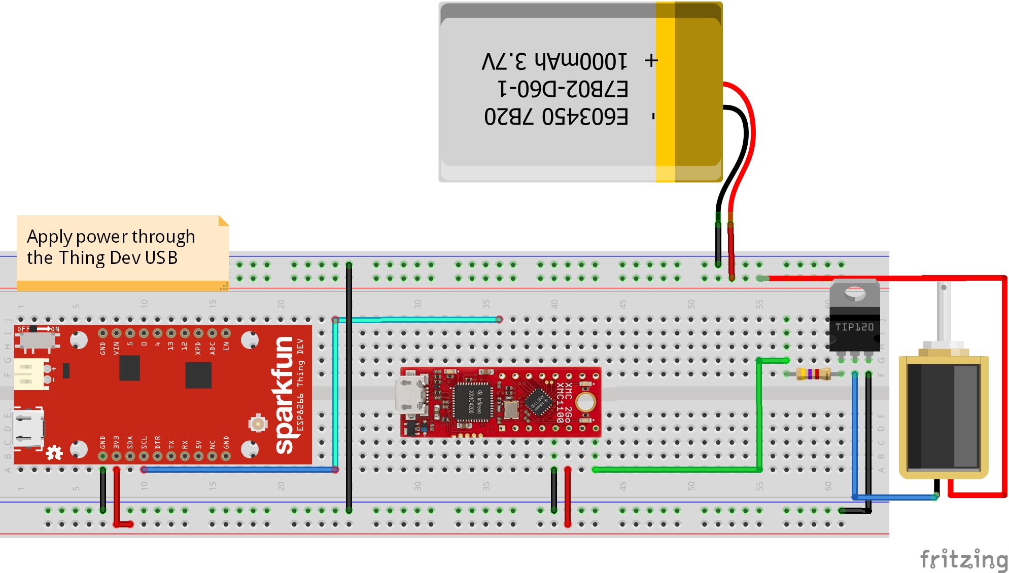
The My door lock function is based on a project that I made for the 'Sensing the World in All Three Dimensions' contest. I think that is a creative way of using a magnet to open a door in a smart building, but you might also want to control it remotely so I implemented that function, too.
In the Wireless communication section I already mentioned how the MQTT communication works in my project, so I'll focus on the new things here. When I click Open, the Home Manager will publish the character '1' to the 'my_door_lock' topic of the MQTT broker. The receiver device is subscribed to this topic and once it receives the '1' it will open the door for a couple of seconds and then close it again.
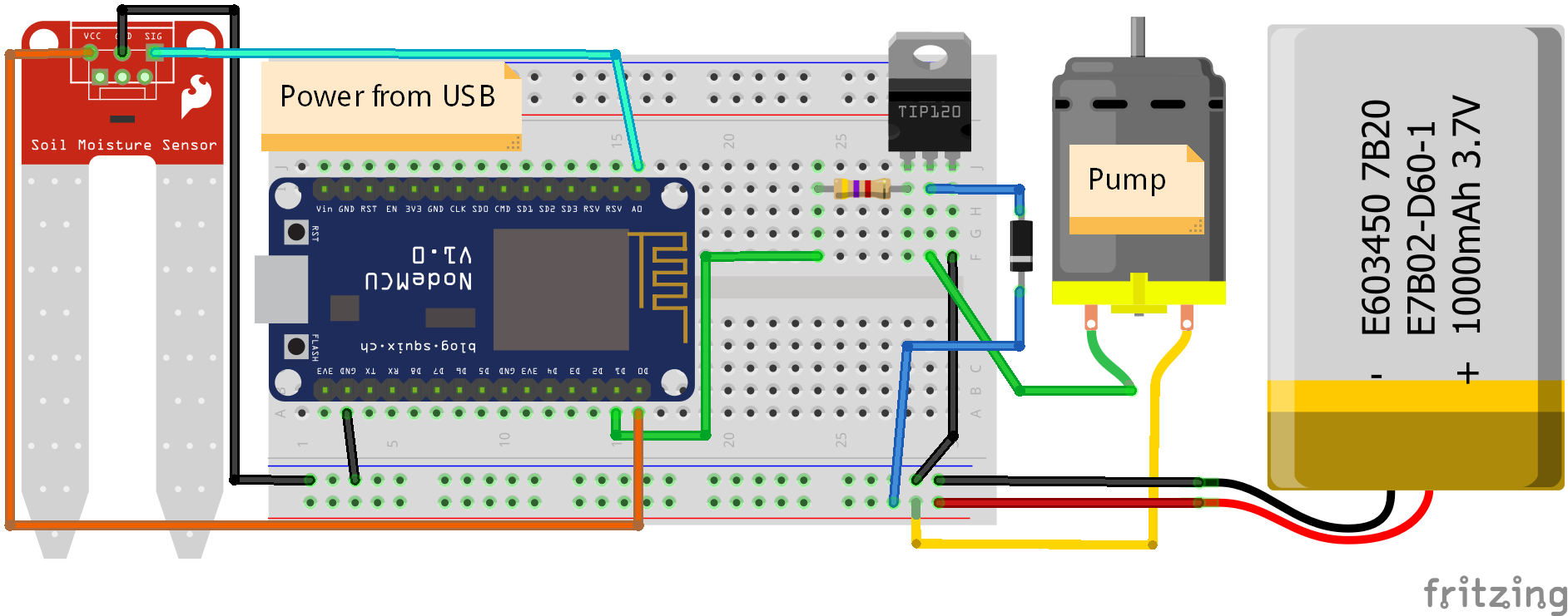
The Irrigating mimosa function works the same, with some extra. I want to know that I need to irrigate the plant. It means that I need to know the moisture level of the plant's soil. The Home Manager is subscribed to the 'mimosa_moisture_level' topic and it periodically updates the Soil moisture level of the Home Manager. This way I'll know if I need to irrigate the plant or not. This is a function that could be easily automated, but due to possible plant killing faults (e.g. bad sensor, tube problems), I'll stay with this system for now. The MQTT topic of this function is 'irrigating_mimosa'.
The reason why soil moisture is 0 on the picture is because I didn't realized that this ESP8266 was turned off when I made this picture and I didn't have time to remake the picture. The contest deadline is too close. This value is the result of a simple ADC read and usually somewhere around 300-500. The sensor is a cheap chinese resistance based moisture sensor.
Mimosas are really awesome plants!
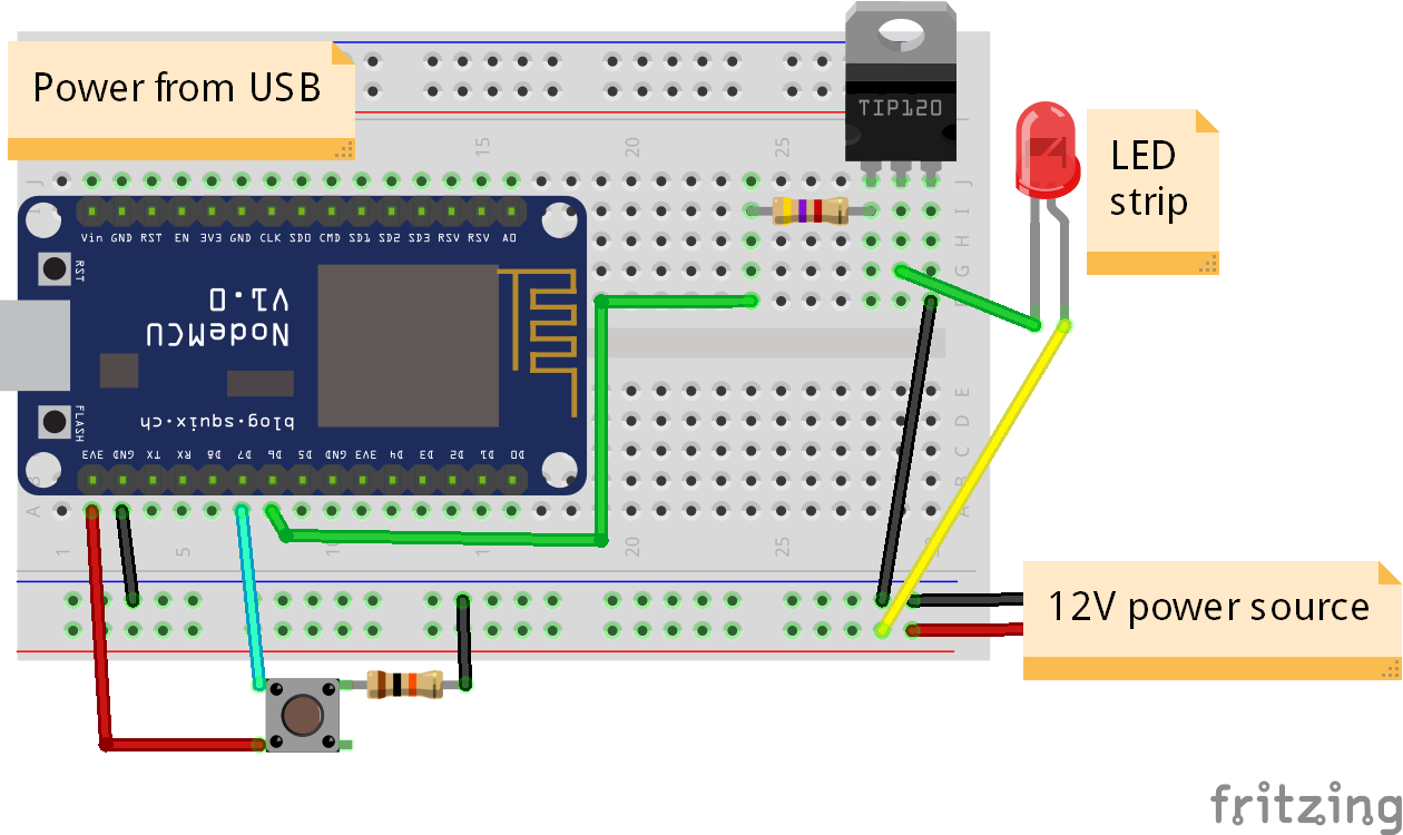
The Kitchen sink lights is a simple on/off switch for LED strips. It will publish a '1' to the 'kitchen_sink_lights' topic when you want to turn the lights on and a '0' when you want to turn the lights off.
The circuit of the kitchen sink lights is the same as the irrigating mimosa circuit, but without the sensor.
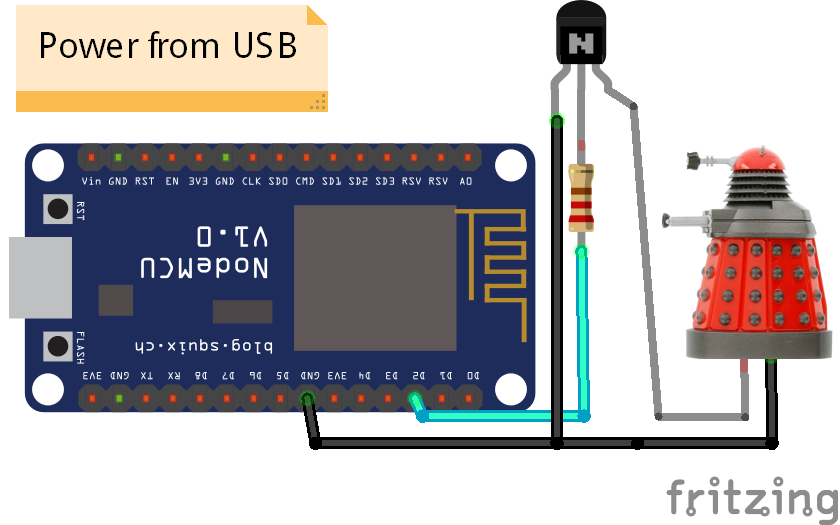
The latest addition to the functions of Home Manager is a Dalek. Originally, it is a badass bottle opener that will scream EXTERMINATE when you open a bottle. I turned it into an IoT Dalek by controlling this shout in the Home Manager.
The Dalek is triggered when you connect the two separate metal part on the bottom. I can easily modify this behavior to work with my system. I didn't want to permanently modify the Dalek (especially because it is not mine), so I just used alligator clips for the connection.
This IoT Dalek is a great device to scare unsuspecting people!
SportThe first function in the Sport sub menu is the Pedometer. I used the MPU6050 for counting the steps. This is the current approach: calculating the total acceleration on the X, Y and Z axis. If the total acceleration is bigger than a threshold then it is counted as a step. It means that you have to place the Home Manager to a place that is moving periodically up and down or back and forward when you are moving. I did some searching and found that you burn 1 calorie with 20 steps. Using this information I display the burnt calories, too. The only accelerometer based pedometers are not too precise so use it accordingly. It looks acceleration only, so any high acceleration move will be counted as a step.
The Jumping is using the same approach, but it has higher thresholds. The higher thresholds mean less or zero false positive data. As people would use a jump counter differently than a pedometer, actually it is quite usable.
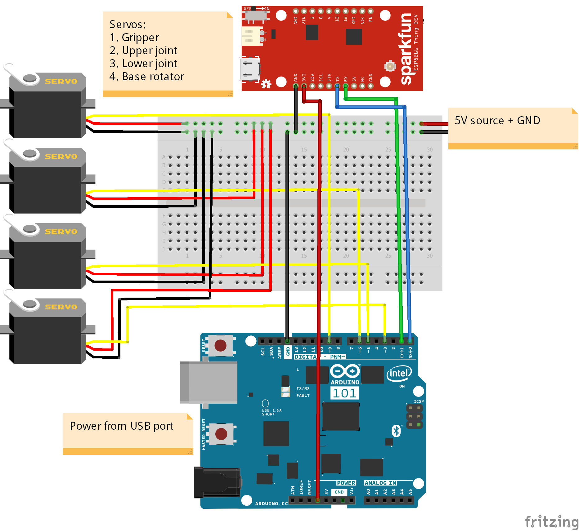
A couple of weeks ago I made a robot arm and controlled it with my Android phone. I figured I could make it work with the Home Manager, 'cause why not? The menu for this feature is different from the others. When you open the Control function, you'll see 4 options, 'Base', 'JntL' (Joint Lower), 'JntU' (Joint Upper) and 'Grip' (Gripper). There will be a rectangle around one of them. The rectangle is used for selecting the desired robot arm segment. Once you click Enter ('Move'), the rectangle will be changed and the Home Manager will move the selected segment using the accelerometer's X angle data. This function is using MQTT messages (topic: 'robot_control'), too. If you reach the desired position just push the Enter again to 'Stop'. If you want, move on to another segment with the Left and Right buttons. This is not the most ideal way to control a robot arm, but it is fun nonetheless!
The Robot Arm sub menu also contains a View sensor data function but it is just a visual feedback of the accelerometer and gyroscope data, received from the MPU6050.
The first function in the safety sub menu is Call for help. Before using this function, you should set these constants in the Home Manager sketch:
#define EMAIL_CONTACT         "test@example.com"
#define EMERGENCY_MSG         "I need help, please come ASAP!"
If you Enter the Call for help function you'll see your contact's email address. Once you click Ask for help (Enter), an email will be sent to 'EMAIL_CONTACT' with the 'EMERGENCY_MSG' message. It is pretty straightforward and works great.
The last function is the Fall detection. If you fall, an email will be sent to 'EMAIL_CONTACT'. You can specify the message by updating FALL_MSG:
#define FALL_MSG "I fell, please help!"
You can enable or disable this function. The fall detection is also using the accelerometers. It works similarly to the pedometer or the jumping, meaning it has the same issue: sensitive to false fall events. I set the threshold quite high and it helps, but still... Nice for a test, but wouldn't bet my life on it in its current state. For proper fall detection probably we need more and different sensors. I didn't made a video about deliberately falling to the floor, again. If you want to see me doing that, just view the video that I made for my previous, similar project.
ConclusionI am really proud of the Home Manager, even if it is just in early alpha stage. I wanted to make a proof of concept project, but it turned out to be so much more than I originally planned. Easy to extend its capabilities so it is likely that I will use it in other projects in the future.
The MAX32620FTHR is a great board and I really love it. I avoided soldering anything to it, because I want to use it in other projects in the future, however it looks like that I have to buy another one because I don't want to disassemble the Home Manager! :D However I still think that they should have included wireless communication in this board.
One thing I'll definitely have to do in the future is refactoring and optimizing the code. I think it is not bad, but the hugely increased functionality left its mark on the code. I'll break it into smaller parts and I'll create an application like behavior for the functions.
Probably I should make some kind of cover for the device, but actually I really like this naked, designless design with the wires and PCB-s, so we'll see.
Thank you for reading! I hope you like my project and it will inspire you to make something great!






_1x_bGT19vVAby.png?auto=compress%2Cformat&w=40&h=40&fit=fillmax&bg=fff&dpr=2)


_3u05Tpwasz.png?auto=compress%2Cformat&w=40&h=40&fit=fillmax&bg=fff&dpr=2)
Comments
Please log in or sign up to comment.