This project is the reincarnation of our beloved clap switch circuits with cool additional features. It's a great project if you like soldering, you're just getting know PSoC Analog Coprocessor and you want to make a project that goes beyond the onboard circuits.
The project will include working with the potentiometer, microphone, some of the onboard sensors and controlling 12V LED strips using Cypress' great board.
The clap switches are with us for some time. This is the easiest project including microphones, so I thought that it will be a good start to work with my new KY-038 Microphone module in a real world application.
Ok, I need something to be controlled by the claps. Around our kitchen sink, the lighting is terrible. It's quite dark when I wash-up the dishes so I decided that I should build a custom lighting there with the clap switch. I don't even have to worry about the water around the switch because I can put the controller anywhere where it will hear my claps.
I need a potentiometer to control the brightness of the LED strip when it's on and of course an LED strip (<1.5m in my case).
It would work perfectly, but I want something more. The Cypress CY8CKIT-48 has a great PIR sensor and a humidity sensor. The PIR sensor will be used to detect the lack of people around the kitchen sink. The humidity sensor will be used to detect high humidity level in the room. Mold caused by mainly the high humidity level in the room is a serious problem in our home, so indicating high humidity level will come in handy.
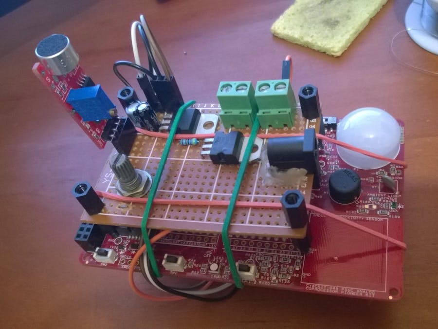
The PCBThis project requires a couple of external circuits, so I created a simple board to eliminate the chaos of breadboards with jumper wires. The board contains a power jack connector. This is providing power for all circuits in the project.
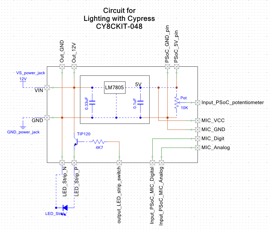
The PCB has multiple connectors. Firstly there's the power jack. It's nothing fancy, just a regular power jack for the 12V power supply. These are also directed to the first 2 green connectors with the screws. Right now these connectors aren't used, but they can come in handy in the future. The other two green connectors with the screws is for the LED strip. These are also 12V connectors and can be switched off or on using a TIP120 transistor, a resistor and one of the male header pins with 5V. The 5V is produced by an LM7805 voltage regulator on the PCB and it provides 5V for the whole system. Other male pins used to access the pins of the microphone and the potentiometer. The female headers is the place for the microphone.
All I have to do is to connect the PCB to the PSoC using some wires. It's very compact. See how to connect the wires on the schematics page.
The 5V regulator actually wouldn't be required, because the CY8CKIT-048 has an onboard regulator but it just wouldn't work at all for me. After lots of documentation reading I came to the conclusion that mine is probably damaged so I had to do some workaround.
I left some free space on the board, so in the future additional circuits can be added to the project with minimal effort. The microphone also can be easily changed to another type. The KY-038's funtionality is limited.
What does the software do?The PCB is placed onto the PSoC, their pins are connected and they are also mechanically connected using 4 jar rubbers. The separator legs are preveting any problems between the board and PSoC. Well, it's befinitely not the most beautiful solution to connect them, but it's quite practical and stable. All I have left is to write the software.
Cypress provides us a bunch of example codes, so I used them for the PIR and the humidity sensors. Using the humidity sensor in this project might seem strange, but I have my reason: high humidity often casues problem for us in winter. We usually don't realize it until some mold appears on the wall. This sensor can alert me to do something against it. I modified the example for the humidity sensor example to switch on the onboard red LED if the humidity level is above 70%.
There are 2 timers/counters in my project. One of them is used to count milliseconds starting when an event is registered. My main function works like this (lights switched off):
- Examining the audio signal. If it is over the threshold then it's an event. so I start the timer and move on to the next step
- Waiting for 40 ms for signal decay
- If after this time the signal is still over the threshold then it is probably not a clap, so resetting the timer comes (=stopping it and resetting the values). If the signal won't go over the threshold then it probably was a clap and move to the next step.
- Wait for another impulse for 1500 ms. If no impulse received by that time, then state reset comes. If another inpulse is received then go to the next step.
- Waiting for 40 ms for signal decay
- If after this time the signal is still over the threshold then it is probably not a clap, so reset comes. If it is registered as a clap then it will change it's state as switched on and resets the timer. It also start the other timer at this point.
The purpose of the other timer is to automatically switch off the lights after 5 minutes if they are switched on. The PIR will play it's role at this part.
If the lights are switched on, the PSoC will examine the PIR and the potentiometer signals. It will update the light levels based on the potentiometer's state using a PWM block. The PIR is used to restart the second timer when it detects movement. It means that it will only switch off after 5 minutes if no movement is detected. If you are around the PIR, then the lights will stay on, but if you leave the room it won't. It saves a lot of energy (no more I forgot to switch off the lights in the morning), so +1 for environmental awareness.
After this part, the humidity reading comes and the PSoC will also send a couple of debug information through UART. EZI2C is very handy, but I still prefer UART for debugging.
Outside main
The microphone registers a bunch of noise. I used the sum of the differences of the last 25 readings to detect the impulses using an array as a FIFO pipeline. It's still a work in progress part as it detects the claps well and minimal false positive readings occur in noisy environment, but still, I have to find a way to deal with them as this is a deal breaker in long term.
The project is definitelly a success! It is very entertaining to switch the lighting on or off with clapping. The only disadvantage of the clap switch is that it is so fun that I am clapping to it all the time :D But I guess I'll get used to this in the future.
There are 2 places where I feel I should make some improvements in the future:
Firstly: The filtering. I'll have get rid of the rare problem of noise switching it on or off. I recommend it to every beginner as this is a fun project, they will get to know PSoC programming in the meantime and in the end they'll have a cool lighting method in the kitchen or anywhere else.
Secondly: Deep sleep mode. Right now the PSoC is constantly on. It doesn't use much power, especially comparing to the LED strip, but still it wastes power when there's nobody around. The PSoC will be in deep sleep to minimize the power consumption. I'll use the D0 pin of the microphone as an interrupt source. It will wake up the PSoC when an event occurs and later it will automatically switch to sleep mode again.


Comments
Please log in or sign up to comment.