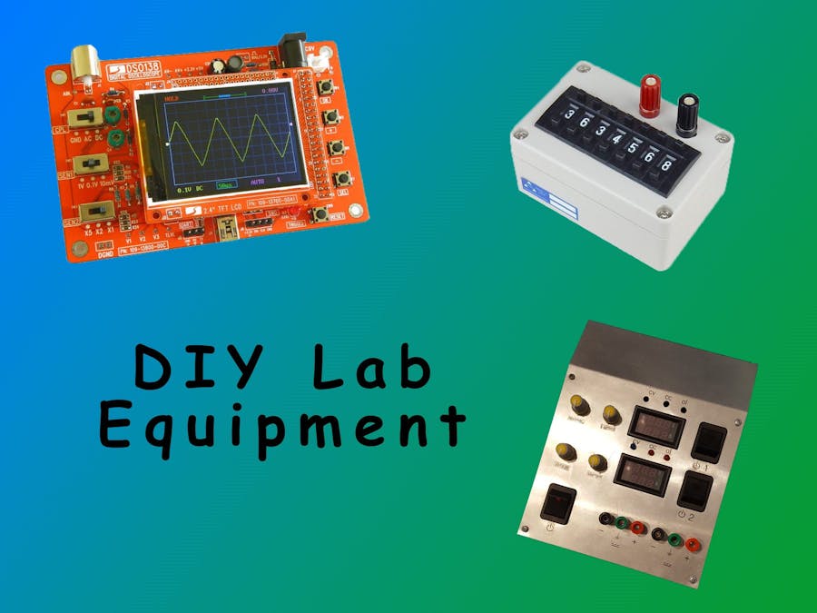
In this project you will learn how to build 4 pieces of essential electronics lab equipment. A two channel power supply, decade box, oscilloscope, signal generator. These pieces of equipment are easy to build and is a good way to get your electronics lab set up on a budget.
Power supplyThis design is for a two channel power supply that is powered by a pre build power supply so is safe for a beginner as there is no need to mess around with high voltage.
My initial design was a dual tracking two channel supply I used a transformer that took 240v AC down to 24V ac I configured the output of the transformer so that it was centre tapped which gave me -24v, 0v & +24v which I then rectified. But unfortunately when I was experimenting I managed to weld the internals of the potentiometer together rendering them useless. so I ditched this idea and decided to use a premade power supply and then stepping down and stepping up this voltage afterwards.
So now onto the final design I chose to use a buck boost converter module that I bought of ebay for about £4 this module is the basis of the power supply. In order for the voltage and current potentiometers to be mounted into the enclosure you will have to desolder the potentiometers on the PCB and connect wires from the PCB to the potentiometer. I also decided to move the LED indicators to the front of the enclosure so I desoldered the LEDs and attached 5mm LEDs in the same way as the potentiometers.
After you are done modifying the module you will want to display the voltage and current for this I used a voltmeter ammeter style display. I connected red wire to the positive of the supply and the yellow wire to the output of the buck boost converter. I then connected the thick red wire to the negative output of the buck boost converter and the thick black wire to the switch for that output. I then soldered a piece of wire from the positive of the buck boost converter to the switch. after that you will need to crimp or solder a piece of wire to the binding posts then solder the wires to the other side of the switch.
These instructions may of been confusing so I included a wiring diagram. once all the circuit is connected repeat this for the other channel then chose the enclosure you would like to then cut out the holes for the display and switch with a saw and drill fitting holes for the LEDs, potentiometers & binding posts.
A decade box Is basically acts like a resistor but you are able to change its resistance with buttons with this design the resistance can vary from 1 ohm to 999999 ohms. I used cheap thumb wheel switches but these posses a resistance within the switch so if you want your resistance output to be more precise use a higher quality thumb wheel switch. Also if you want your output to be more precise you could use +-1% resistors compared to the regular +-5% resistors I used.
To make the decade box all you have to do is solder a resistor from one pin of the thumbwheel switch to the next. After you have completed all your thumb wheel switch assemblies solder a short piece of wire from the end of one switch to the start of the next repeat this until you have connected all your switch assemblies together solder a piece of wire from the very first switch to a binding post then do the same to the end of the set of switches. After all your connections are made chose a suitable enclosure and mount the switches and binding posts like the picture shown bellow.
This piece of equipment is very easy to build all you have to do is buy a oscilloscope kit and solder all the parts onto the PCB and then check that the voltages are correct then your done. A fully functional oscilloscope for only £20 it does have its limitations but should be adequate to get you started in your early electronics projects. I decided to put mine in a acrylic case to protect it.
The signal generator is also a easy to build kit. just solder all the parts on to the PCB then your left with a signal generator that works perfectly for low frequency needs but it does have a lot of distortion at higher frequencies and the output current is low due to a high output impedance. I chose to mount my signal generator in an enclosure this meant that I had to add wires to the LCD, buttons and connectors. This kit is powered by +5v +12v -12v so I recommend you get one of these cheap power supply's.
I thank PCBWay for the partnership.
PCBWay is a cheap reliable service where you can get your PCBs manufactured. All the PCBs are high quality and the engineers are very helpful and will resolve any problems you may have quickly. Sign up today and get a $5 welcome bonus.
Check Out PCBWay Hackster page.
WebsiteCheck out more of my other projects on my website.


Comments
Please log in or sign up to comment.