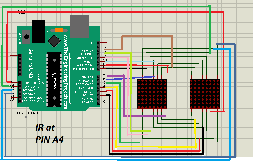
//Simply connect all the pins as shown in diagram
//You need to connect 220 ohm resistor to save the led matrix.
#define ROW_1 2
#define ROW_2 3
#define ROW_3 4
#define ROW_4 5
#define ROW_5 6
#define ROW_6 7
#define ROW_7 8
#define ROW_8 9

#define COL_1 10
#define COL_2 11
#define COL_3 12
#define COL_4 13
#define COL_5 A0
#define COL_6 A1
#define COL_7 A2
#define COL_8 A3

const byte rows[] = {ROW_1, ROW_2, ROW_3, ROW_4, ROW_5, ROW_6, ROW_7, ROW_8};

//if you want to change the design, put your changes in design line wise
byte OPEN[] =
{
  B00111100,                             //    ****
  B01000010,                             //   *    *
  B10011001,                             //  *  **  *
  B10111101,                             //  * **** *
  B10111101,                             //  * **** *
  B10011001,                             //  *  **  *
  B01000010,                             //   *    *
  B00111100                              //    ****
};

byte CLOSE[] =
{
  B00111100,                             //    ****
  B01000010,                             //   *    *
  B10000001,                             //  *      *
  B10000001,                             //  *      *
  B10000001,                             //  *      *
  B10000001,                             //  *      *
  B01000010,                             //   *    *
  B00111100                              //    ****
};


void setup()
{
  Serial.begin(9600);
  pinMode(2, OUTPUT);
  pinMode(3, OUTPUT);
  pinMode(4, OUTPUT);
  pinMode(5, OUTPUT);
  pinMode(6, OUTPUT);
  pinMode(7, OUTPUT);
  pinMode(8, OUTPUT);
  pinMode(9, OUTPUT);
  pinMode(10, OUTPUT);
  pinMode(11, OUTPUT);
  pinMode(12, OUTPUT);
  pinMode(13, OUTPUT);
  pinMode(A0, OUTPUT);
  pinMode(A1, OUTPUT);
  pinMode(A2, OUTPUT);
  pinMode(A3, OUTPUT);

  pinMode(A4, INPUT);
}

void loop()
{
  if((digitalRead(A4))==0)
  {
    drawScreen(OPEN);
  }
  else
  {
    drawScreen(CLOSE);
  }
}

void  drawScreen(byte buffer2[])
{
  // Turn on each row in series
  for (byte i = 0; i < 8; i++)
  {
    setColumns(buffer2[i]); // Set columns for this specific row
    digitalWrite(rows[i], HIGH);
    digitalWrite(rows[i], LOW);
  }
}


void setColumns(byte b)
{
  digitalWrite(COL_1, (~b >> 0) & 0x01); // Get the 1st bit: 10000000
  digitalWrite(COL_2, (~b >> 1) & 0x01); // Get the 2nd bit: 01000000
  digitalWrite(COL_3, (~b >> 2) & 0x01); // Get the 3rd bit: 00100000
  digitalWrite(COL_4, (~b >> 3) & 0x01); // Get the 4th bit: 00010000
  digitalWrite(COL_5, (~b >> 4) & 0x01); // Get the 5th bit: 00001000
  digitalWrite(COL_6, (~b >> 5) & 0x01); // Get the 6th bit: 00000100
  digitalWrite(COL_7, (~b >> 6) & 0x01); // Get the 7th bit: 00000010
  digitalWrite(COL_8, (~b >> 7) & 0x01); // Get the 8th bit: 00000001
  // If the polarity of your matrix is the opposite of mine
  // remove all the '~' above.
}


_ztBMuBhMHo.jpg?auto=compress%2Cformat&w=48&h=48&fit=fill&bg=ffffff)


Comments
Please log in or sign up to comment.