I love long road trips on holidays with family or friends. But spending too long at the wheel leads to drowsiness and fatigue sooner or later. Unattentiveness of the driver is a major cause of road accidents. It is advised that a person spend no more than 6 hours a day driving. But there is not really a sure way to tell when a person is feeling tired, other than self-intuition, and that is no exact science, nor can it be relied upon to prevent mishaps.
So I decided to build an automatic solution, one which can monitor the driver continuously and alert them when it detects signs of losing concentration or attentiveness, advising the driver to take a break and rest. For this, I decided to use Infineon's development kits specially designed for edge AI applications, along with a small 2 MP camera module I had lying from a previous project, to quickly come up with a prototype application.
Hardware usedThe PSoC™ 62S2 Wi-Fi BT Pioneer Kit(CY8CKIT-062S2-43012) is a low-cost hardware platform that enables design and debug of the PSoC™ 62 MCU and the Murata 1LV Module (CYW43012 Wi-Fi + Bluetooth Combo Chip).
Features:
- CY8CMOD-062S2-43012 carrier module that contains: a) PSoC 6 MCU (CY8C624ABZI-S2D44), and b) Murata 1LV ultra-small 2.4/5.0-GHz WLAN and Bluetooth functionality module based on CYW43012
- 512-Mbit external Quad SPI NOR Flash that provides a fast, expandable memory for data and code
- 4-Mbit Quad SPI ferroelectric random-access memory (F-RAM)
- KitProg3 onboard SWD programmer/debugger with USB-UART and USB-I2C bridge functionality
- CapSense touch-sensing slider (5 elements), two buttons, based on self-capacitance (CSD) and mutual-capacitance (CSX) sensing
- A micro-B connector for USB device interface for PSoC 6 MCU
- 1.8 V and 3.3 V operation of PSoC 6 MCU is supported
- Two user LEDs, an RGB LED, two user buttons, and a reset button for PSoC 6 MCU
- A potentiometer
- One Mode selection button and one Status LED for KitProg3
- A microSD Card holder
The IoT sense expansion kitis a low-cost Arduino™ UNO compatible shield board that can be used to easily interface a variety of sensors with the PSoC™ 6 MCU platform, specifically targeted for audio and machine learning applications.
Features:
- Digital XENSIV™ MEMS Microphone(s)
- Digital XENSIV Barometric Air Pressure Sensor
- Bosch 9-axis Absolute Orientation Sensor
- Piezo MEMS Analog Microphone
- Audio Codec and headset jack
- OLED Display Module
The ESP32-CAM development board has a very competitive small-sized camera module board that can operate independently as a minimum system with a footprint of only 27*40. It comes with OV2640, a 2MP camera module.
Features:
- The smallest 802.11b/g/n Wi-Fi BT SoC Module
- Low power 32-bit CPU, can also serve the application processor
- Up to 160MHz clock speed, Summary computing power up to 600 DMIPS
- Built-in 520 KB SRAM, external 4MPSRAM
- Supports UART/SPI/I2C/PWM/ADC/DAC
- Support OV2640 and OV7670 cameras, Built-in Flash lamp.
- Support image WiFI upload
- Support TF card
- Embedded Lwip and FreeRTOS
- Supports STA/AP/STA+AP operation mode
- Support for serial port local and remote firmware upgrades (FOTA)
I found a promising dataset and model for predicting driver drowsiness over at Kaggle and decided to use it for the first iteration of the project. The particular notebook is linked below:
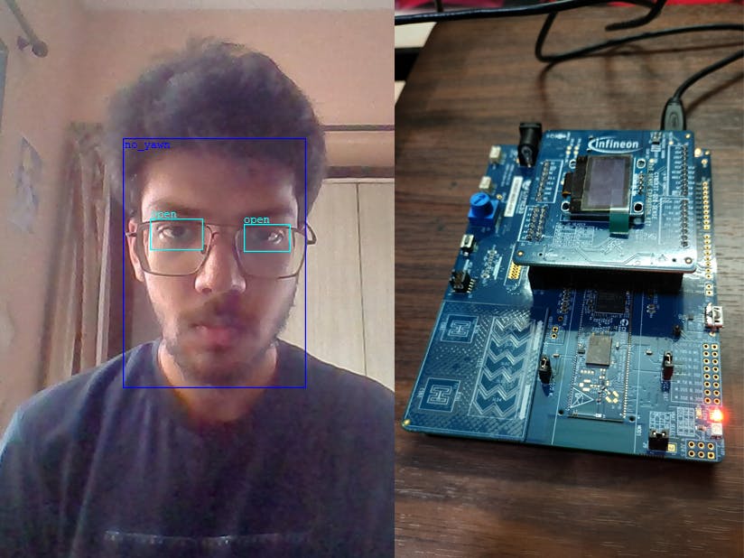
The model works by extracting visual artefacts including the eyes and mouth of the driver from the camera frame, and classifying them as being open/close and whether the driver is yawning using a convolutional neural network (CNN).
On the particular dataset, an accuracy of 94.8% was achieved on the train set and 96.2% on the validation set. Further, the model was used to predict some unlabelled inputs from my webcam to a very good degree of accuracy.
The results of these classifications over time are then used as the basis for predicting the driver's alertness.
ModusToolboxFrom there I started a project using ModusToolbox™ Software by Infineon.
It provides an easy and interactive way to transform the Keras model file into an embedded C++ library. I used the Machine_Learning_Neural_Network_Profiler example to get started and recommend doing the same to follow along.
Using the ML Configurator tool, I generated the source code and validated it against the dataset. As the dataset consists of image data, I had to preprocess it separately into feature arrays before feeding it into the model.
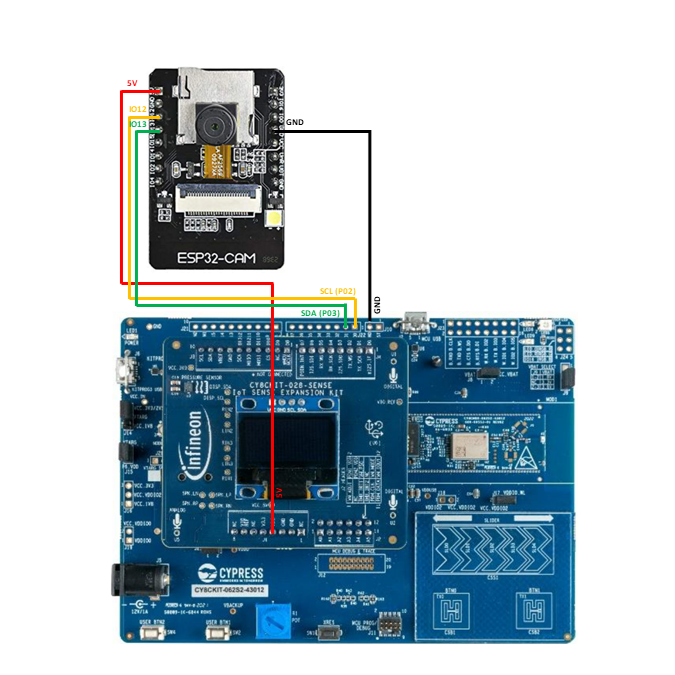
To set up the input on ESP32-CAM module, I used Arduino IDE to program it. Pictures are taken from the OV2640 camera module at a frequency of 15 Hz. To relay the data to PSoC board, I opted to use I2C serial communication. Since both hardware I2C buses were already in use by the camera module, I used a soft I2C implementation using IO12 and IO13 pins.
The following tutorial explains how to get the ESP32 libraries working on the IDE. ESP32-CAM Video Streaming and Face Recognition with Arduino IDE | Random Nerd Tutorials
Use the AI-Thinker model for the part number. Connect pin IO0 to GND while flashing code to the module and disconnect it afterwards. I used an Arduino board to flash to the module but any USB-TTL device will work.
Display and I/OOn the PSoC side, from the available GPIO pins I chose Serial Communication Block 0 for communication with ESP32, which were pins P02 and P03, as shown, as these were also readily exposed on the discovery board. Any other combination of pins can also be chosen, changing the code accordingly.
I referred the following page for information about pin configuration: MTB CAT1 Peripheral driver library: I2C (SCB) (infineon.github.io)
The sense expansion kit is easier to set up, as it can be directly mounted on the Arduino pin headers. To use the OLED display, the following libraries need to be added to the project: CY8CKIT-028-SENSE and emwin.
Additionally, in the Makefile, the following line needs to be added:
COMPONENTS=EMWIN_NOSNTSFinally, in main.c, include both of these libraries to get started with modifying the OLED display.
#include "cy8ckit_028_sense.h"
#include "GUI.h"
For more information, check out: Infineon/CY8CKIT-028-SENSE (github.com)
WiFiI initially planned to program the device to ping a Wifi network if the driver becomes drowsy. This would be intercepted by an Android application to further alert the driver using an alarm.
However, I didn't get to this part in time for the contest and will be updating this in the coming week.
Final electrical schematicFor demonstration, I am streaming the video from my webcam instead of ESP32, which works quite similarly, to show the video stream being captured as well. The output from the application is also transmitted serially for display on the terminal.
Thank youI hope you enjoyed this project. Please leave behind any feedback in the comments.


Comments
Please log in or sign up to comment.