


Hardware components | ||||||
_ztBMuBhMHo.jpg?auto=compress%2Cformat&w=48&h=48&fit=fill&bg=ffffff) |
| × | 1 | |||
 |
| × | 1 | |||
| × | 1 | ||||
| × | 1 | ||||
| × | 1 | ||||
| × | 1 | ||||
| × | 1 | ||||
I wanted to spruce up my room a little bit, so I decided to opt for some basic LED strips. Rather than just light things statically, I also wanted to give the lights the ability to react to music playing through a speaker. Specifically, my goal was to produce a lighting system that reacts to the frequency of the sound. I couldn't find any simple software and hardware instructions to do this, so here we are!
The main goal of this project is simplicity. You can construct this for under $40 in less than an hour.
Step 1: PartsThis project can be constructed entirely with breadboard-compatible components all sourced from Sparkfun. Look at the parts section for the full list, but one thing to note is that it's certainly possible to substitute the parts here for others.
Almost any microcontroller will work here, although it should be at least as fast as an Arduino Uno (16 MHz ATmega328). The rate-limiting step of the response rate is the Fourier transform, so a much faster microcontroller like something based on the Cortex M-series will have blazing speeds. You will also need to figure out register settings for whatever microcontroller you select, so I recommend something based on the ATmega328.
Any light strip compatible with Adafruit's NeoPixel library will work. Lastly, you will likely need two power supplies (one for the lights, and one for the microcontroller).
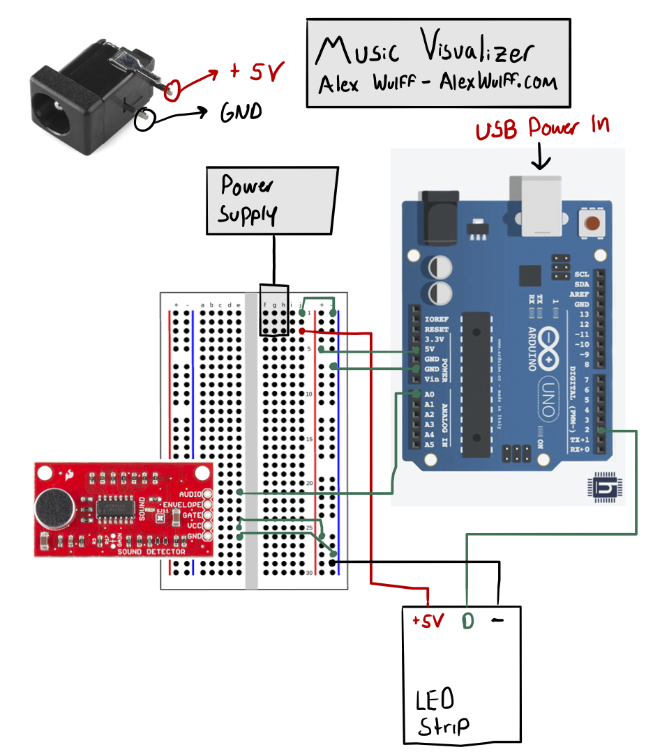
Step 2: CircuitAs you can see, the circuit is not particularly complicated. See the diagram above for more details, but the basic connections are listed below:
- 5V Power Supply -> Barrel Jack -> LED Strip Vin
- 5V Power Supply -> Barrel Jack -> LED Strip Ground & Microcontroller Ground
- Microcontroller 5V Output -> Microphone Module Vin
- Microcontroller Ground -> Microphone Module Ground
- Microcontroller Pin 2 -> LED Strip Data In
- Microcontroller A0 -> Microphone Module Audio Out
Points to Note:
- Connecting the LED Strip: The SparkFun LED strip listed uses red, green and white wires. Red is power in, ground is data in, and white is ground. You can insert jumper wires directly into the female connector pins to connect this. Ensure that you connect the right end - there's an arrow that indicates in which direction the data must flow.
- Separate Power Supplies: I found that when the lights were hooked up to the same power source as the microcontroller the sound analysis became extremely noisy. I attribute this to the LED strip causing voltage swings. For this reason, I recommend powering your lights with a separate power supply.
- Level-Shifted Audio Output: This SparkFun module is nice because it has components to both amplify audio from the microphone and center the audio level at half the supply voltage. If you use a different module it might not accomplish both these tasks, so be careful. If the audio is not amplified and the level is not shifted you likely won't have great results.
- Using Multiple Strips: It's certainly possible to connect multiple LED strips together. If you do this, however, note that you will likely need a power source that can supply a great deal of current (3+ amps).
You can find the software in the attachments section, and here on GitHub. This software requires the following libraries, both of which can be installed directly from the Arduino library manager:
- arduinoFFT
- Adafruit NeoPixel
One item to note about the software is sampling. The Nyquist Sampling Theorem dictates that in order to capture a signal you need to sample it at least twice as fast as the fastest-varying components of the signal. If we want to capture audio signals, which contain meaningful frequencies to about 20 kHz, we need to sample at a rate greater than 40 kHz. The Arduino function analogRead is too slow for this, so we must manipulate some microcontroller registers to access analog to digital converter (ADC) data directly. Credit to this tutorial for the register manipulation code. This code is device specific, so you will need to modify these settings to work on your own microcontroller if you don't utilize an ATmega328-based board.
We actually extract frequency information using a Fast Fourier transform (FFT). If you input an array of N real samples (i.e. without phase information) in the time domain to the FFT function, you will get out an array of N points in the frequency domain, half of which are redundant. Since we sampled at around 40 kHz, the maximum frequency component will be at around 20 kHz (per the sampling theorem mentioned above). My code uses 64 samples, so we get a frequency resolution of 20000/(64/2) = 625 Hz.
I then extract the largest magnitude frequency component, and change the light color based on the frequency of this component. I map this frequency to a range of between 0 and 255, and create colors as follows, where the X axis is the mapped frequency, and the Y axis is the magnitude of each color channel:
Lowest frequencies are represented in green, and the highest frequencies are represented in red. Frequencies in between are represented in combinations of colors. I quite like this visualization, but others are certainly possible. Another thing to note is that I only display colors if the signal is above a certain volume. If it's not, the strip will display a dim white color. I found it to be quite annoying to have the lights flickering when there's no music playing. You can adjust the sound_thresh variable accordingly.
Things to Adjust:
- The variable loop_num is the number of times the FFT will be calculated and averaged together. If you find that your lights are too jittery, increase this number!
- The variable sound_thresh is the sound threshold at which the lights will start changing colors. If you find that the music needs to be really loud for the lights to start reacting you can lower this number, or if the lights flicker when you don't want them to then you can increase this number.
- The variable samples is the size of the input vector to the Fourier transform. Try playing around with this number, but keep it a power of 2.
Compile and upload the code to your microcontroller, and you should be all set!
Step 4: Installation and Next StepsThat's basically it - if you wired everything correctly, you now have a functional music visualizer. Installation should be simple - just pick a spot where you have access to a power outlet. Most strips have adhesive backing, so you can stick them just about anywhere. There's obviously a ton of things you can do to modify this project. Here are some ideas:
- Changing the Colors: If you don't like my color choices, you can change this software to create your own!
- Using Volume instead of Frequency: The SparkFun sound detector module also has a pin called "ENVELOPE, " which is a measure of the overall volume of the sound. You could sample this pin with analogRead, remove the FFT code, and instead modify the colors based on sound level.


_3u05Tpwasz.png?auto=compress%2Cformat&w=40&h=40&fit=fillmax&bg=fff&dpr=2)
Comments
Please log in or sign up to comment.