I made this project to measure the water level in a rainwater tank, but the same concept can be used to measure almost anything using an ultrasonic sensor (water, snow, trash bin, etc.).
This project focuses on a low power solution. My tank is not easily accessible so I don't want to have to change the batteries too often! My objective is to reach a year of operation with a reasonable battery capacity.
Due to the location of the cistern, LoRaWAN / The Things Network was a logical choice for the transmission of the measures.
LoRaWAN nodeAny low power node will do, so pick the one you are comfortable with.
I used a Mini-LoRa, as I have good experience with it in other projects but any (low power) node will do.
I like LiFePO4 batteries. Their nominal voltage is 3.2V, which means you can use them with 3.3V micro-controllers without LDO/regulator and save a bit on power consumption.
For this project I selected a 18650 size LiFePO4 battery. Mine is only 1800 mAh, but that should be enough.
MaxBotix Inc. produces a wide range of high quality ultrasonic rangefinders which are easy to interface trough their serial interface.
You can use the Sensor Selector Guide to find the right sensor for your particular need.
Sensors are available in several version, you need to select one providing Serial TTL output (If you choose RS232, you will have to invert de signal!)
You will need a mounting kit (a lock nut and a sealing o-ring) to secure the sensor to the enclosure.
If you need precision readings, you can also get the MaxBotix HR-MaxTemp External Temperature Compensation Sensor.
Going low powerLet's do some measurements:
The MaxBotix sensor draws about 40mA while ranging and a couple of mA in sleep mode.
While this is not a lot, we definitely need to bring the sleep power down for our battery operated node.
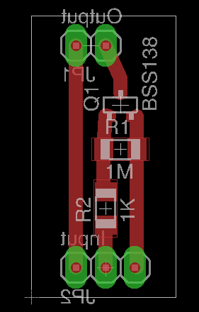
To achieve this we use a N-Channel Logic Level FET as 'low-side' switch to control the power for the sensor. A small breakout board will make the assembly easy.
The current will flow only when the control signal is high.
You can get the board from a PCB manufacturer, as it is rather simple and for a quick turnaround I use a CNC to mill the board:
It does not look very nice, but it works well: we have now less than 1µA in sleep mode:
The serial data format used by the sensor is 9600 baud, 8 data bits, no parity, and one stop bit.Each measurement is in the format Rxxxx<0x0D>, xxxx being the distance measured in mm.
As the sensor is powered on for each measurement, it will also print its boot message. A typical session will look like this:
SCXL-MaxSonarWRMT
PN:MBxxxx
Copyright 2011-2017
MaxBotix Inc.
RoHSv23b 068  0517
TempI
R1599
R1600
...
The Arduino SoftwareSerial library can be used to read data from the sensor, but SoftwareSerial() needs two pins (rxPin, txPin) while we only need one. To save a GPIO pin we are using a stripped-down version of SoftwareSerial which only implements the read: SoftwareSerialRead.
The code for reading one data sample:
// Hardware configuration
const uint8_t sensorReadPin = 4;	// Serial output from the sensor
const uint8_t sensorEnablePin = A3;	// Pin driving the MOSFET to control power

// In "stream" mode, data is available every 1.83 seconds.
// Set a timeout to ensure we don't stay forever in read loop, but long enough
// to capture at least a complete frame.
const unsigned long timeout = 3000;

SoftwareSerialRead sensor_serial(sensorReadPin);

void sensor_setup() {
	// Configure port for MOSFET control
	pinMode(sensorEnablePin, OUTPUT);
	digitalWrite(sensorEnablePin, LOW);
	// Sensor serial port
	sensor_serial.begin(9600);
}

/*
 * get_sensor_data()
 *
 * Return one sensor reading or zero in case of timeout or frame error
 *
 */
uint16_t get_sensor_data() {
	unsigned long start_time = millis();
	bool start_frame = false;
	uint16_t distance = 0;
	char p1 = '0';
	char p2 = '0';

        // Power sensor on
	digitalWrite(sensorEnablePin, HIGH);

	// Wait for the start of frame marker
	while (!start_frame && (millis() - start_time < timeout)) {
		if (sensor_serial.available()) {
			char c = sensor_serial.read();
			if (c == 'R' && p1 == '\r' && p2 != '.') {
				start_frame = true;
			} else {
				p2 = p1;
				p1 = c;
			}
		}
	}

	if (start_frame) {
		// Next 4 characters are the distance
		uint8_t i = 0;
		while (i < 4 && (millis() - start_time < timeout)) {
			if (sensor_serial.available()) {
				char c = sensor_serial.read();
				if ('0' <= c && c <= '9') {
					distance = distance * 10 + (c - '0');
					i++;
				} else {
					// Corrupted data
					i = 4;
					distance = 0;
					Serial.print(F("Data corruption: "));
					Serial.println(c);
				}
			}
		}
		if (i < 4){
			Serial.println(F("Timeout while reading frame"));
			distance = 0;
		}
	} else {
		Serial.println(F("Timeout while waiting for start frame"));
	}

	// Disable sensor
	digitalWrite(sensorEnablePin, LOW);
	return distance;
}
(See also lp-water-level)
Battery life expectationIf we assume a power consumption of 45mA during 4 seconds for sampling and sending data, the following table shows the battery life expectation if we measure every 15 or 30 minutes.
The actual battery capacity is most probably less than the nominal 1800 mAh, but the power consumption figures used are maximized which should compensate.
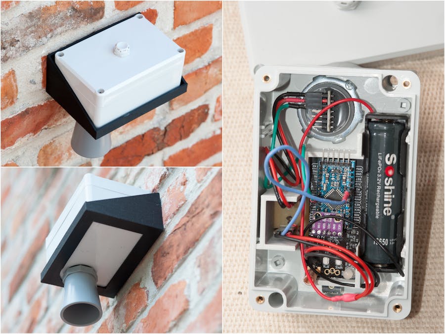
Putting everything togetherAll components have been tested, it is time to put everything in the enclosure.
We add a Bosch BME280 environmental sensor on the I2C bus; this is not necessary, but it is a nice to have!
To hold all the parts in place in the enclosure we are using a 3D-printed skeleton
Everything fits well together:
Back to the 3D printer for the bracket to secure the enclosure in the water tank:
The water level node in place:
The node reports:
- The water level -- distance from the sensor (in dm to fit the analog in put range of the Cayenne LPP format)
- The BME280 environmental data (temperature, pressure, humidity)
- Battery level
- The node awake time of the previous iteration (used to model battery life)


Comments