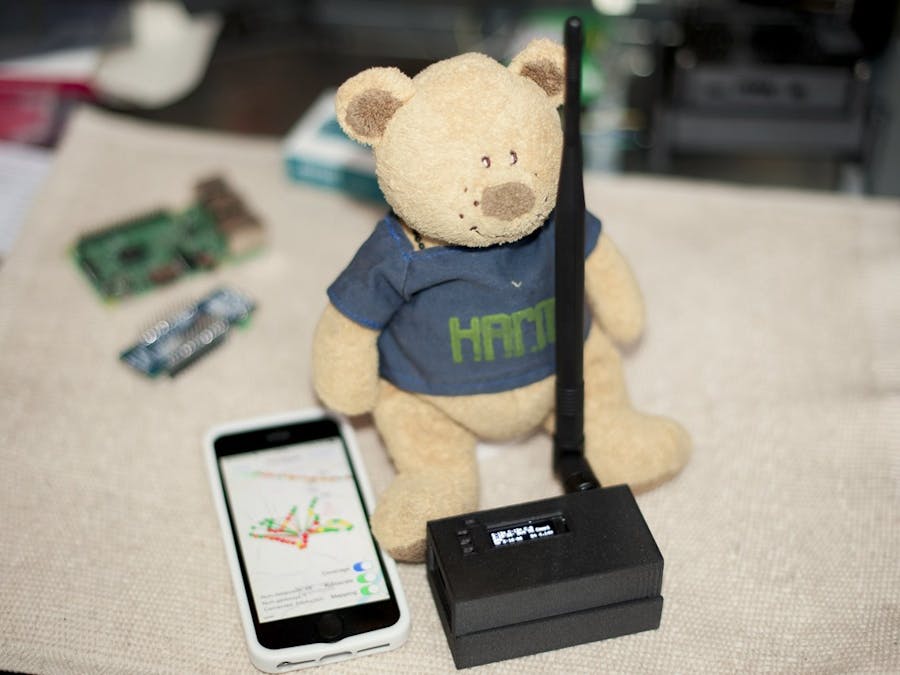
Having a new gateway in place for The Things Network (TTN), I wanted to test its coverage in urban environment.
This can easily be achieved with the TTN Mapper project, a simple LoRaWan node and an Android or IOS smartphone.
My first tests were a bit difficult, because you don't really know if your device is able to register, when it sends a packet and so on. So I eventually decided to assemble a simple node with a small screen for the feedback.
The Adafruit Feather M0 with RFM95 LoRa Radio together with the OLED FeatherWing was an easy and logical choice. It almost runs 'out-of-the-box'.
This small project describes how to get your node online in just a couple of hours (a bit more if you decide to print the enclosure!).
The Adafruit LoRa Feather and its OLED FeatherWing are almost ready for TTN! The are two things which we need to look at.
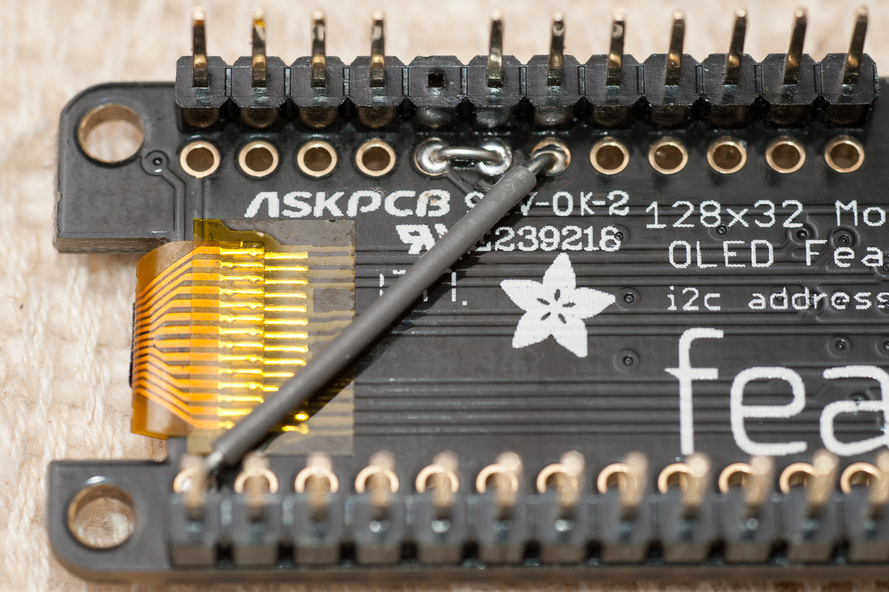
First, the Button A of the FeatherWing is routed to Digital #9 pin of the M0 micro-controller. But this pin is also Analog A7 which can be used to measure battery voltage! The Arduino sketch is currently not using the buttons, but to avoid any issue we re-route Button A to Digital #10.
The other point is more important: the LMIC (LoraMAC-in-C) Arduino library which is used to communicate with TTN needs access to the DIO1 pin of the RFM95 radio chip. The Feather exposes this pin (labeled IO1 on the board) but it is not routed to the M0 micro-controller. We need to route IO1 to a free Digital pin; we will use Digital #11.
Enough for the reading, let's assemble the electronics!
Solder the headers first. For the FeatherWing, pull out the pin corresponding to Button A (see pictures).
Note that I am using 7mm female headers on the Feather, if you are using taller headers the device won't fit in the 3D printed enclosure.
If you go with an external antenna, solder the uFL connector under the Feather board, otherwise solder a 82mm wire (for the 868Mhz frequency plan). For more details see Antenna Options on the Adafruit website.
Last but not least, we need to solder two bridges to re-route Button A and DIO1. This can easily be done on the FeatherWing:
Stack the Display on top of the micro-controller and you are done!
You can print an enclosure or jump directly to the Software paragraph to test your node.
EnclosureIf you have (access to) a 3D printer, I designed a simple enclosure to protect the boards and secure the antenna.
The STL and the STEP source files are available on YouMagine. It is a 3 parts assembly, no screw needed. It is easy to print, just don't use a material which is too brittle.
And the final assembly:
Before compiling the small Arduino sketch, we need to ensure we have the environment and the required libraries in place -- I am referring to the Adafruit website for most parts as they are well documented:
- Arduino IDE setup (Support for Adafruit boards)
- SAMD Support (Support for the M0 micro-controller)
- Adafruit OLED libraries: install the Adafruit SSD1306 and GFX libraries (the FeatherOLED library is not needed)
- Arduino-LMIC library: download and install this library just like you did for the other ones.
It is recommended to slow down the speed of the SPI bus from 10MHz to 8MHz. In the source code of the Arduino-LMIC library. Edit src/hal/hal.cpp line 77 and change 10E6 to 8E6 -- from
static const SPISettings settings(10E6, MSBFIRST, SPI_MODE0);
to
static const SPISettings settings(8E6, MSBFIRST, SPI_MODE0);
By default, the Arduino-LMIC library is configured for an RFM95 radio using the European 868MHz frequency plan. If you use the US 915MHz frequency plan, you will need to edit src/lmic/config.h and change
#define CFG_eu868 1
//#define CFG_us915 1
into
//#define CFG_eu868 1
#define CFG_us915 1
Note: if you have re-routed DIO1 to a different pin than Digital #11 as suggested above, you will need to update the pin mappings in ttn_mapper.cpp.
Other than that, the ttn-mapper script only needs to be configured with your Application and Device keys.
In the TTN Console:
- Create an Application if you don't already have one
- Register a new Device in this Application. As RFM95 / M0 chips don't have unique id/serial, let the TTN console assign you an EUI for your Device.
- In the Device Overview screen take note of the Device EUI, Application EUI and App Key.
In the Arduino IDE, open the ttn-mapper sketch:
- Rename
ttn_secrets_template.hintottn_secrets.h
- Fill in the fields with the data from the console. For the Device EUI and Application EUI you need to reverse the byte order! The App Key is copied as-is.
That's it!
Compile and upload the sketch. After reset, you should see the TTN logo, the device will then join the network and send a packet every minute.
The display shows:
- Top line - S: number of packets sent
- Top line - C: number of confirmed sent packets (this does not mean it has been received by a gateway, just that the send operation is completed)
- Top line - E: error count (should be 0!)
- Middle lines: last action issued or event received and its timestamp
- Bottom line: device uptime and battery voltage indicator.
To actually start mapping your gateway coverage, install and configure the TTN Mapper app on your smartphone (see the TTN Mapper FAQ for more info), and have a walk with your new ans shiny node...
Send packet intervalOnce the node joins the network it will send one packet every minute. You can adjust this interval in ttn_mapper.cpp, but you have to respect the LoRaWan/TTN duty cycle!
// Send packet interval (in seconds) -- respect duty cycle!
const uint8_t send_packet_interval = 60;
If CAYENNE_LPP is defined in ttn_mapper.cpp (default) the node will send its battery voltage in CayenneLPP format.
// Uncomment the following line to send Battery Voltage instead of '*' as payload
#define CAYENNE_LPP
If you configure your application to recognize CayenneLPP, the payload will be displayed in the TTN console as analog_in_1:
Should you prefer a smaller payload, comment out the CAYENNE_LPP define in the source.


Comments
Please log in or sign up to comment.