


Hardware components | ||||||
_ztBMuBhMHo.jpg?auto=compress%2Cformat&w=48&h=48&fit=fill&bg=ffffff) |
| × | 1 | |||
 |
| × | 12 | |||
 |
| × | 16 | |||
 |
| × | 2 | |||
Software apps and online services | ||||||
 |
| |||||
Hand tools and fabrication machines | ||||||
 |
| |||||
Connecting an LCD to an Arduino can sometimes be a bit tedious due to the number of wires and components required, such as potentiometers and resistors.
To streamline this process, I've created a custom LCD Breakout Board that simplifies these connections.
This board includes :
1. Two potentiometers to:
a. Control the backlight brightness
b. Adjust the contrast (text brightness)
2. Pins for common positive and negative terminals
3. Separate Data pins
Making it easier to hook up your LCD to an Arduino using just a few jumper cables.
(NOTE - You don’t need any libraries to use this breakout board.)
In this tutorial, I will walk you through how to make and then use this breakout board to quickly set up an LCD with your Arduino.
StepsStep 1: Prototype Before You Solder
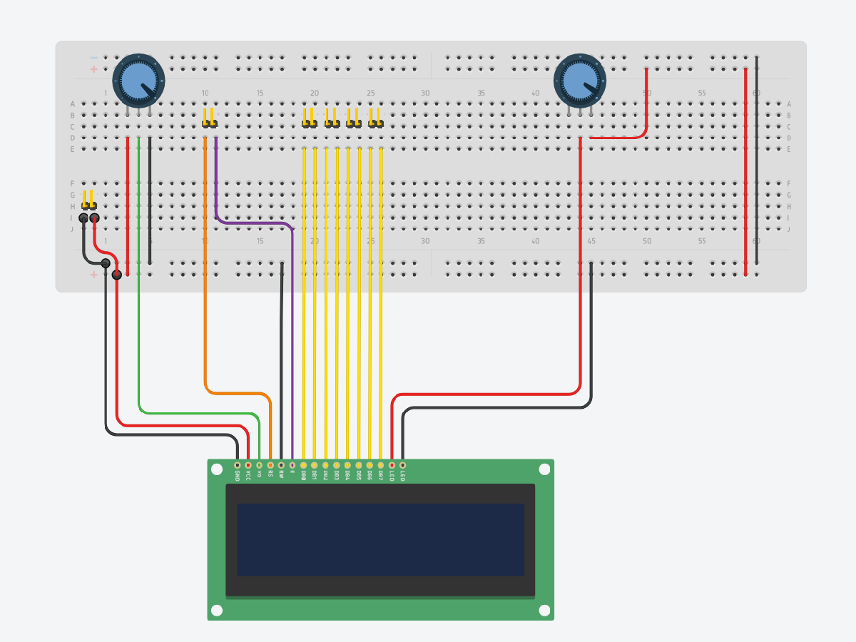
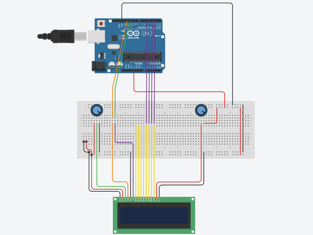
Before you finalize your design by soldering the components onto the perf board, you can first try prototyping the circuit on a breadboard.
You can use this circuit diagram for reference:
This allows you to test the connections, make adjustments, and ensure everything functions as expected.
During this stage, you can experiment with different configurations, such as adjusting potentiometer values, modifying the layout, or adding/removing functionality to better suit your specific needs.
Step 2: Solder the components on the perf board
Once you're satisfied with the setup, you can then proceed to solder everything onto your perf-board while keeping the connections clean and simple.
Optional: Mark Pins for Easy Identification
To make the wiring process easier and avoid confusion, you can use a permanent marker to label the pins on the breakout board. Simply mark the pin names (e.g. VCC, GND, RS, EN, D4, D5, etc.) directly on the board or near the pin headers. This step is optional, but it can save time and reduce errors during setup, especially if you plan to disconnect and reconnect components frequently.
Optional: Add Spacer Screws for LCD Support
To provide additional support and stability for the LCD, you can add spacer screws of appropriate size to the board. This will help prevent the LCD from shifting or flexing during use. When adding the screws, ensure that you carefully drill the holes in the board without damaging any existing connections. Be mindful of the placement to avoid interfering with the circuit's functionality. This step is optional but can improve the durability and reliability of your setup.
Optional: Design a Custom PCB
For a more refined and durable circuit, you can design a custom PCB. This allows for a cleaner layout and consistent connections. Use PCB design software like Eagle or KiCAD to create your design, and then have it manufactured and assembled.
Testing:
Step 1: Verify Connections on the Breakout Board
Ensure your custom LCD interface board is ready, with all components properly soldered and connected. Check for any possible shorts between pins.
Step 2: Connect the LCD to the Custom Interface Board
Attach the 16x2 LCD display to the breakout board.
(Optional: Tighten the spacer screws to provide support to the LCD)
Step 3: Connect the breakout Board to the Arduino
Using jumper wires, connect the following pins from the breakout board to the Arduino:
VCC from the board to the 5V pin on the Arduino.
GND from the board to the GND pin on the Arduino.
RS to Arduino pin 12
EN to Arduino pin 11.
D4 to Arduino pin 5.
D5 to Arduino pin 4.
D6 to Arduino pin 3.
D7 to Arduino pin 2.
Step 4: Upload the Code
Upload the given code to your Arduino using the Arduino IDE.
Step 5: Power Up and Adjust Contrast
Power up your Arduino by connecting it to your computer or a power supply. Use the potentiometers on the breakout board to adjust the contrast of the LCD until the text is clearly visible.
Step 6: Test Your Setup
The LCD begins with a start-up message (“LCD Custom Board”) followed by a loading animation (“Loading...”). It then runs a scrolling test where a solid block character moves across both lines of the display, visually checking all character positions (pixels). After the test completes, the screen shows the message “Test Completed”. If everything is working correctly, you've successfully used your custom LCD breakout board to simplify the LCD-Arduino connection!
Final LCD Output:
Watch the video to see the custom LCD interface board in action.
Troubleshooting:
No Display: Check all connections and ensure the LCD is properly seated on the breakout board.
Dim/No Text: Adjust the potentiometer to change the contrast.
Conclusion:
By using this custom LCD breakout board, you can save time and reduce the complexity of connecting an LCD to your Arduino. This project is perfect for those who frequently use LCDs in their Arduino projects and want a more streamlined setup process.
Feel free to modify and expand upon this design to suit your specific needs!


Comments
Please log in or sign up to comment.