


Hardware components | ||||||
 |
| × | 1 | |||
 |
| × | 1 | |||
 |
| × | 1 | |||
 |
| × | 1 | |||
 |
| × | 1 | |||
Software apps and online services | ||||||
| ||||||
This project is based on a project by Project Hub user Alex Glow
NeoPixels are a beautiful and versatile way to add programmable RGB LEDs to your project. They come in rings, sticks, strips, matrices, and more.
Each pixel is made up of several separate colored diodes: RGB, or RGBW if there's a pure-white channel. And each RGB "pixel" has its own little controller chip. If you just hook up the power, nothing will happen – you have to send data over a PWM pin to make these live.
Here's a quick guide to setting them up with the Arduino IoT Cloud.
For this project you will need to use an IoT Cloud enabled Arduino board, we are using an Arduino Nano 33 IoT.
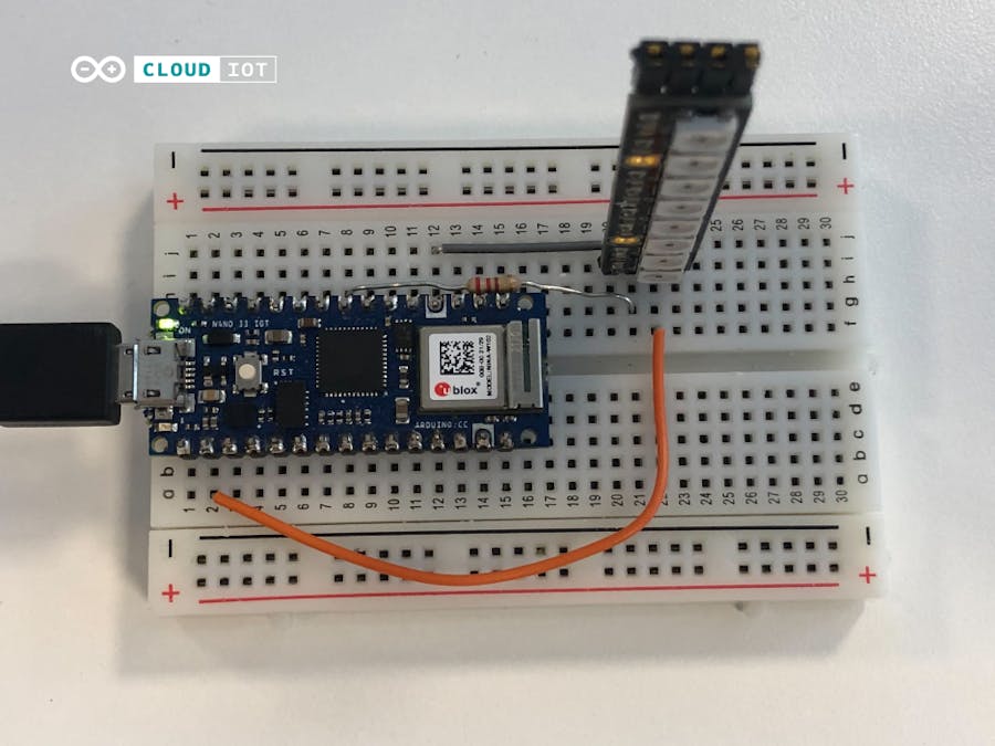
Step 1: WiringStart off by connecting the components to the breadboard. Follow the step by step guide included below.
- Place the Arduino board on the breadboard.
- Place the Neopixel strip on the breadboard.
- Connect the GND pin on the Neopixel strip to GND on the Arduino board.
- Connect the 5VDC pin on the Neopixel strip to 3.3V on the Arduino board.
- Place a 10kOhm resistor connecting the NeoPixel strip to pin 5 on the Arduino board. It needs to be connected to a PWM pin, otherwise it won’t work!
When you have completed the circuit, it should look like this:
To get started with this step, you will need some very basic knowledge of the Arduino IoT Cloud service. If you have built any previous project using the service, then don’t worry, you know all that you need to know.
If you are new to the Arduino IoT Cloud, then take some time to read through the Getting started page and you will be good to go. There are also a bunch of tutorials available if needed.
In the cloud, you need to create a new Thing, then configure your device and network.
You should then add a variable. Name it Neopixel. It should be of the variable type Colored Light. It needs to have both read & write permissions, as you will be using the dashboard to change the color and brightness of the light.
Now, you will need to create a dashboard to be able to send information to the Arduino board. Go to the Dashboards section, and create a new Dashboard.
Inside, create a new widget: To make the creation of the control widget super easy, we will create the widget from the variable. To do this, follow these steps:
- Press “Add” to open the drop-down menu, then click into the “Things” tab
- Select the thing where you have created the Colored Light Variable, in our case we have called it “Neopixel”, in the menu that pops up, make sure the box for your Colored Light Variable is checked, then confirm and create the widgets.
- Done!
These widgets will, for now, not function, since we have not yet uploaded the sketch to our board, which we will do in the next step.
Step 3: CodeTo run this project, we need to include a few libraries to make life much easier for us, write these lines of code directly below the automatically included `thingProperties.h` file. If you want to skip ahead, you will find the entire sketch at the bottom of this page.
#include <Adafruit_NeoPixel.h>
#ifdef __AVR__
#include <avr/power.h>
#endif
Now, we want to define which pin we’ll use to control the lights, and the amount of Neopixels that are in our light strip. We also want to pass this information to the library that is handling the light strip. We will use pin 5, and in the neopixel strip we are using, there are 8 Neopixels. Define this by adding the following lines of code after the inclusion of the libraries
#define PIN            5
#define NUMPIXELS      8
Adafruit_NeoPixel pixels = Adafruit_NeoPixel(NUMPIXELS, PIN, NEO_GRB + NEO_KHZ800);
With the previous step in place, we are ready to initialise the Neopixel library. Add the following line of code inside of the setup function to run once at the start of the program.
pixels.begin();The loop function will actually remain empty, we don’t want to run code all the time without reason. Instead, the `onNeopixelChange` function at the bottom of the sketch that will be run every time the values in the Colored Light Variable that we added before creating our Dashboard changes. The rest of our code will be written inside this function.
We start by setting up variables to hold the values for the red, green and blue values, and we read the input from the widget.
    uint8_t r, g, b;
    neopixel.getValue().getRGB(r, g, b);
We then check if the lamp is supposed to be on or not. If it is toggled on, we start a for loop to pass the values that are set in the widget to each of the Neopixels in the strip.
if (neopixel.getSwitch()) {
    Serial.println("R:" + String(r) + " G:" + String(g) + " B:" + String(b));
    //prints the current R, G, B values
    for (int i = 0; i < NUMPIXELS; i++) {
        // pixels.Color takes RGB values, from 0,0,0 up to 255,255,255
        pixels.setPixelColor(i, pixels.Color(r, g, b));
        pixels.show(); // This sends the updated pixel color to the hardware.
    }
}
If the switch is toggled off, however, we need to turn the lights off. So we add “else”-conditional with another for loop to the end of what we just added.
else {
    Serial.println("Lamp Off");
    //the following code simply turns everything off
    for (int i = 0; i < NUMPIXELS; i++) {
        // pixels.Color takes RGB values, from 0,0,0 up to 255,255,255
        pixels.setPixelColor(i, pixels.Color(0, 0, 0));
        pixels.show(); // This sends the updated pixel color to the hardware.
    }
}
The full sketch can be found below, at the end of the page.
ConclusionOnce you upload this sketch, you are done, and can control the light strip from the IoT Cloud! Enjoy!


Comments
Please log in or sign up to comment.