


Hardware components | ||||||
_ztBMuBhMHo.jpg?auto=compress%2Cformat&w=48&h=48&fit=fill&bg=ffffff) |
| × | 1 | |||
| × | 1 | ||||
| × | 1 | ||||
1. Download the library
3. Code
Read moreIn order to run this sketch on your Arduino board you have to download the Adafruit NeoPixel library.
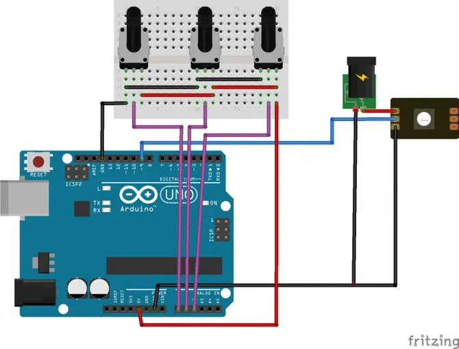
2. How does it work?The sketch is very simple: there are 3 potentiometers attached to three different analog inputs (A0, A1 and A2). Each one control the amount of color (Red Green and Blue respectively) in 1 meter of addressable WS2812 LEDs.
For sake of simplicity in the following layout only one LED is reported.
Attention: Please make sure to supply the strip using an external 5V power supply as reported in the layout!
Here the code! Upload it and start to play with colors!
/*
Color addressable LEDs control using Adafruit NeoPixel library
Parts required:
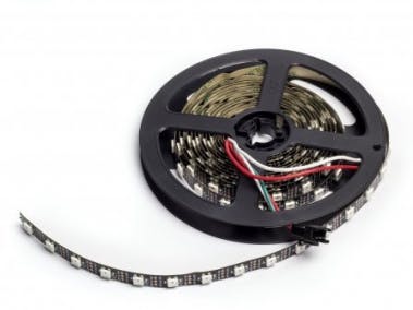
1m strip of addressable LEDs http://store.arduino.cc/products/C000083
Created 28 November 2014
by Arturo Guadalupi <a.guadalupi@arduino.cc>
This example code is part of the public domain
*/
#include <Adafruit_NeoPixel.h>
const int NUMPIXELS = 60; //number of LEDs in 1m
const int LEDsPin = 9; // LEDs connected to digital pin 9
const int redPotPin = A0; // pin to control red
const int greenPotPin = A1; // pin to control green
const int bluePotPin = A2; // pin to control blue
int redValue = 0; // value to write to the red LED
int greenValue = 0; // value to write to the green LED
int blueValue = 0; // value to write to the blue LED
int redPotValue = 0; // variable to hold the value from the red pot
int greenPotValue = 0; // variable to hold the value from the green pot
int bluePotValue = 0; // variable to hold the value from the blue pot
// When we setup the NeoPixel library, we tell it how many pixels, and which pin to use to send signals.
Adafruit_NeoPixel pixels = Adafruit_NeoPixel(NUMPIXELS, PIN, NEO_GRB + NEO_KHZ800);
void setup() {
// initialize serial communications at 9600 bps:
Serial.begin(9600);
// set the digital pin as output
pinMode(LEDsPin, OUTPUT);
}
void loop() {
// Read the pots first:
// read the value from the red pot control:
redPotValue = analogRead(redPotPin);
// give the ADC a moment to settle
delay(5);
// read the value from the green pot control:
greenPotValue = analogRead(greenPotPin);
// give the ADC a moment to settle
delay(5);
// read the value from the blue pot control:
bluePotValue = analogRead(bluePotPin);
// print out the values to the serial monitor
Serial.print("raw sensor Values \t red: ");
Serial.print(redPotValue);
Serial.print("\t green: ");
Serial.print(greenPotValue);
Serial.print("\t Blue: ");
Serial.println(bluePotValue);
/*
In order to use the values from the pots for the LEDs,
you need to do some math. The ADC provides a 10-bit number,
but analogWrite() uses 8 bits. You'll want to divide your
sensor readings by 4 to keep them in range of the output.
*/
redValue = map(redPotValue, 0, 1023, 0, 255);
greenValue = map(greenPotValue, 0, 1023, 0, 255);
blueValue = map(bluePotValue, 0, 1023, 0, 255);;
// print out the mapped values
Serial.print("Mapped sensor Values \t red: ");
Serial.print(redValue);
Serial.print("\t green: ");
Serial.print(greenValue);
Serial.print("\t Blue: ");
Serial.println(blueValue);
// For a set of NeoPixels the first NeoPixel is 0, second is 1, all the way up to the count of pixels minus one.
for (int i = 0; i < NUMPIXELS; i++) {
// pixels.Color takes RGB values, from 0,0,0 up to 255,255,255
pixels.setPixelColor(i, pixels.Color(redValue, greenValue, blueValue));
pixels.show(); // This sends the updated pixel color to the hardware.
delay(50); // Delay for a period of time (in milliseconds).
}
}


Comments
Please log in or sign up to comment.