


Hardware components | ||||||
 |
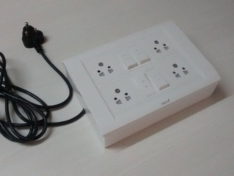
| × | 1 | |||
The Node MCU is an open source ESP8266 based Wifi enabled IoT platform for everyone. What we have done is created a four relay board for it and the coolest part is that board also has a 100-240V-AC to 5V-DC Power supply on board so you will be able to connect it directly to AC mains while creating a Wifi enabled switch board. It also has a header where you will be able to connect i2c based devices (Something like an I2C based OLED ) although we will still need to test this.
A brief specification of the board is as mentioned below.
- It comes with a header where you can plug in Node MCU Module.
- Four Relays to connect four AC/DC loads and both NC/NO connectors of the relay are provided.
- SSID and Password can be set directly from the mobile app.
- Can be pre-programmed with MQTT for Networking/Home automation integration.
- 100-240VAC or 5VDC select able input.
- LED for Testing which is connected to a GPIO and also as indicator when the relay go on /off.
- Dimensions of the board are 145 X 60 X 18 mm.
I have created a few diagrams to help you out with the wiring .The first diagram is a logical diagram .You will find on one side a red colored vertical line that is the AC phase/Line and on the right there is another vertical line which is the neutral. On the four relay board both NC (Normally Closed Circuit) and NO (Normally Open Circuit) of the relay are available. The two way switch has three terminals - NC, NO, Common and is usually as shown in one of the diagrams.The reason for using a two way switch is to have both physical as well as using you mobile phone to turn on/off some appliance.
The logical diagram shows how the connections are made. Let me show you the status and the load condition based on the status of relay and the switch
Relay Switch Load Relay & Switch
NO NC NO NC Status Status
0 1 0 1 OFF BOTH OFF
1 0 0 1 ON RELAY ON
1 0 1 0 OFF BOTH ON
0 1 1 0 ON SWITCH ON
I hope this is clear. The load here in my case will be the three pin socket you may also connect the load(Fan, TV, light etc) directly but make sure you take appropriate measures while connecting to the main.
Step 2: TCP/IP based Android - Arduino Code to control the switch boardYou can find both android app and the Arduino code on our GITHUB page.
I have shared some images and video for your understanding.
The initial set up is simple just install the apk on your android phone.
Search for ESP/AI-Tinker Hot spot on your phone.Connect to it. After that start the app Wifi Four Relay board.
Enter 192.168.4.1 in the ip text box.
Enter 80 in the port text box and then press connect .Here you will find four buttons you can click it and the light/load should turn on/off.
If you want to connect it to your wifi router without changing the program you will need to send the following command.
SSID:xxxx:yyyy:
xxxx will be your Wifi SSID
yyyy will be your Wifi Password
Step 3: Mqtt BasicMQTT (Message Queuing & Telemetry Transport) is a publish-subscribe based "light weight" messaging protocol for use on top of the TCP/IP protocol. It is designed for connections with remote locations where a "small code footprint" is required or the network bandwidth is limited. The publish-subscribe messaging pattern requires a message broker(Some thing like a server). The broker is responsible for distributing messages to interested clients based on the topic of a message.
For details you can visit this site http://mqtt.org/
In My application I have used a board called Onion Omega
Its a good board if you wish to install just the MQTT Broker but if you wish to develop a full fledged Home automation system I suggest you do it using Raspberry Pi and Open HAB.
Onion Omega runs a flavor of linux called Open WRT (Its a custom Linux flavor which is popularly used on many routers) .You will need to install the broker on this using terminal via ssh (Use Putty on Windows).
Refer this link to install MQTT broker Mosquitto on OpenWRT
http://mosquitto.org/2011/08/mosquitto-on-openwrt/
Here are the steps:
opkg updateopkg install mosquitto mosquitto-client libmosquitto
This will install the broker and client on Onion Omega. After it installs you can try simple commands using two terminal /putty windows. On one of the window/terminal just type
mosquitto_sub -d -t msg/box
And on the other just type
mosquitto_pub -d -t msg/box -m "Hello World"
you should get "Hello World" on the other first window(Where you entered mosquitto_sub -d -t hello/world).
Here "msg/box" is called a Topic this can be any thing (eg. can be sensor/analog or sensor/digital or RelayControl etc) .One can either subscribe to a topic(first command did that) or can publish to a topic(second command published "Hello World" to the topic msg/box) once that is sent to the broker all the devices will receive message "Hello World" if and only if they have subscribed to that topic.
Also note if you are using some other device where your broker is not installed on you will need to add the broker ip in the command as shown below.
mosquitto_sub -h YOUR_BROKER_IP -d -t msg/box
mosquitto_pub -h YOUR_BROKER_IP -d -t msg/box-m "Hello World"
Step 4: MQTT code and Linking it with other devices like Onion Omega or PiPlease Watch the video to get some idea.
What I am trying to achieve here is I have two types of Esp8266 based board one is the node mcu four relay board and the other is Attiny85 +Esp-01 based board ,both of them should communicate with each other through the broker .You can refer to this instructable for details regarding the Attiny85+Esp-01 Board.I have loaded both with MQTT client code.
Attiny85+Esp-01 Board has an additional gpio free which I have used and have connected a PIR sensor .One of the image will show how the box looks.
The Broker is installed on Onion Omega which runs Open WRT.
The preferred android mobile app is My Mqtt but most of it is text based . I also do have a modified app but its is not full proof. Will upload the code once it is usable
Here are the commands I have integrated
+ATon --will turn on the relay of the Attiny85 +Esp-01 board
+AToff --will turn off the relay of the Attiny85 +Esp-01 board
+ATstatus --Will give you the status of the PIR sensor (High /Low)
+ATstart ---Will start notifying to the topic "Relay_Control" change in status of the PIR sensor (you will receive PIR HIGH ,PIR LOW message on your mobile ) .It also turns on/off the relay of the Attiny85+ Esp-01 board
+ATstop ---This will stop the above notification and also makes the relay independent from the PIR sensors output
on01 ---Node MCU four relay boards first relay turns ON
on02 ---Node MCU four relay boards second relay turns ON
on03 ---Node MCU four relay boards third relay turns ON
on04 ---Node MCU four relay boards fourth relay turns ON
ledon ---Node MCU four relay boards led turns ON
ledoff ---Node MCU four relay boards led turns OFF
off01 ---Node MCU four relay boards first relay turns OFF
off02 ---Node MCU four relay boards second relay turns OFF
off03 ---Node MCU four relay boards third relay turns OFF
off04 ---Node MCU four relay boards fourth relay turns OFF
The above commands can also be sent or see by publishing or subscribing from a mqtt client machine using the below command
mosquitto_sub -h YOUR_BROKER_IP -d -t Relay_Control // to subscribe to Relay_Control Topic
mosquitto_pub -h YOUR_BROKER_IP -d -t Relay_Control -m "xxx" //to send commands to Relay_Control Topic
xxx here will be any of the previously mentioned commands eg off01, on01 etc
Please make sure you have installed at least mosquitto-client, libmosquitto packages on the client computer.
I will still need some time to update the content will do that as I develop the application .As of now just posting it .If you have any question please do comment and probably I will modify the instructable to clarify your doubts
Thank you


Comments
Please log in or sign up to comment.