


Hardware components | ||||||
 |
| × | 12 | |||
 |
| × | 1 | |||
This fun project demos the use of Hexabitz solid state relay (SSR) modules-H0FR60 in a large array. I will also show you how to disassemble the modules and re-assemble them again in a completely different configuration without writing any code!
What is it?This project is a fun way to start your Hexabitz development using H0FR60 solid state relay (SSR) modules and learn how we build relatively large arrays and the way they can be automatically configured and controlled without writing code. 12 SSR modules are assembled in the first configuration and then the array is reconfigured into a different shape with only 10 SSRs. To make the system stand-alone, I also added a single 3.3V / 1A DC-DC module (H03R00) to power the modules themselves from a wall AC-DC adapter.
Estimated hardware build time: 10-15 minutes
Estimated software development time: 5 minutes
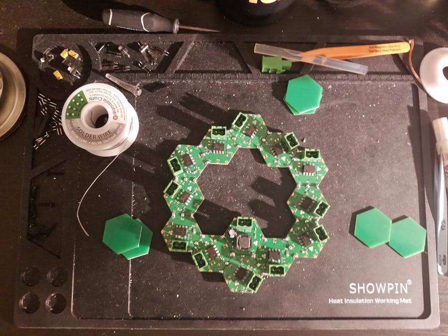
Building and configuring the arrayFirst let's start assembling the relay modules in the preferred configuration. I chose this beautiful hexagonal shape that fits 12 modules with all the green connectors (relay switch terminals) on the outside perimeter. Add the H03R00 module to power the array if you are planning for a stand-lone system. If not, you can power directly from your USB-UART cable!
Connect to one of the modules and run the module Command Line Interface (CLI). I used our lovely wired Kelvin clamp to communicate with modules without soldering! Once you type the explore command in the CLI, the indicator LEDs start dancing performing the exploration algorithm to find and identify their neighbors, swap ports, communicate their states and build the array routing table. Once succeeded, the array topology and relevant information will be stored in each module's MCU Flash memory so that whenever you power down and power up again, all modules know their locations and connections in the array.
Now we're ready to test if everything is working well! Using the broadcast command all.toggle, all relays toggle their output from OFF to ON state. The yellow LEDs mean that the relay output is turned ON, i.e., the contacts are closed. The command was broadcasted to all connected modules.
Modules can be grouped together and given a name or alias as well. Commands can then be targeted only to the group members, i.e., the CLI command can be multicasted as well as broadcasted.. Grouped module don't have to be adjacent or of the same type. You can for example, group all LEDs together and all relays together. Or you can group the relays driving heaters in a group called heaters and the ones driving fans in a group called fans regardless of their physical location in the array. All you need then to control heaters and fans is to call them by name:
group heaters #1 #4 #5
group fans #2 #8
heaters.on
fans.toggle
You can also split the relays into groups based on their load location: south room, north room etc.
Can't decide what to build? Get twice the fun by disassembling the array and going into same process again for a completely different shape (and even quantity)! Before you disassemble your old array, make sure to erase the old topology (i.e. routing table) from module non-volatile memory by executing the following command from any single module:
default array
This will be broadcasted and remove the stored topology from all modules.
Desoldering the modules is as easy as heating the solder joint until it splits in half. You can clean the residual solder or leave it there since you'll be assembling the modules again. Here is your new board minutes later :)
Check the entire process in this video.


Comments
Please log in or sign up to comment.