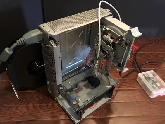
If you got smashed playing multi-player xbox 360 games like 'Halo' or 'Call of Duty' in 2008 / 2009 by a gamer with the handle "Kernal BT"... then your opportunity for revenge has past you by. I've smashed my game unit in an epic tear-down and transformed it into a miniature 3D printer for under $75.00.
It's not too difficult to disassemble the unit into component parts. This gives you a chance to look at what has dominated your time in a more abstract way. As an engineer, I immediately see the useful galvanized metal frame and a DVD player with some moving mechanical motors. I continue by breaking out the DVD drive and use a Dremel to drill some holes in the thicker metal frame that will provide the mechanical structure of my newly fabricated 3D printer.
I've looked at various 3D printers for inspiring designs, but this post is a borderline exercise in building a robotic structure that will push your comfort zone.
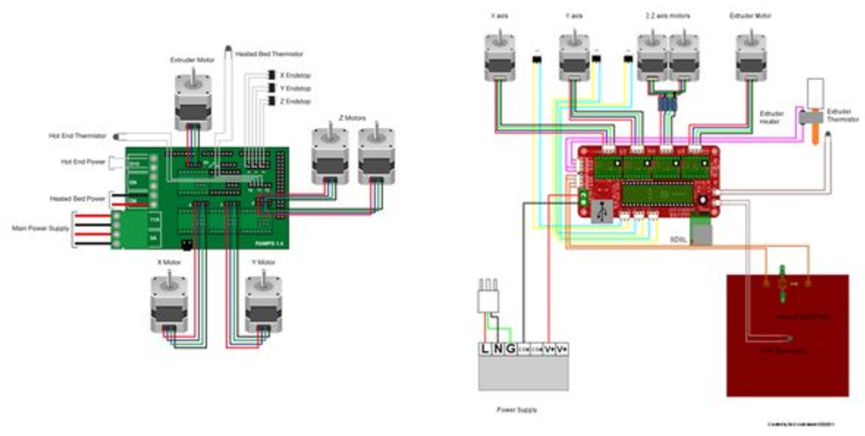
Looking at designs of relevant 3D Printers always puts the project into perspective. Above is the mindmap overview for RepRap 3D printer components. Here are the overall design schematics of a RepRap 3D printer system with parts of both the infrastructure (Electrical and Mechanical including Extruder) and software functions that will be needed to get our printer to operate as intended.
InventoryHere's the inventory that I have from the tear down. I avoid re-using the patented xbox chip sets, because I don't want to be banned from the professional gamer leagues in the future among other issues, but it is an easy substitute using an IoT device.
Before continuing on this journey you’re going to need knowledge of 'how to solder' and some additional parts that are not available from this initial gold mine. Now scavengers let's target what is missing:
- Filament - ABS or PLA of various thickness ($20.00 USD)
- Hot-End of the system – ($7.99 USD)
- Extruder - Drive Gear grabs filament, Stepper Motor advances the filament, PTFE (Teflon ™) tube directs path and Idler holds pressure when applied to the 'hot-end' ($14.00 USD)
- Acrylic panel - Heated Bed (Alternative) as the target of delivery ($3.19 USD)
- Controller - IoT offering (i.e. Raspberry Pi or Arduino) - MKS Gen V1.4 ($35.00 USD)
- Stepper Driver - Precision motor control, connect a 4-wire stepper motor & microcontroller. (included in MKS GEN v1.4)
- Printer Control Software for calibration and coordination
Now if you're looking for a good place to acquire motors, just ask a molecular biology solution provider. Huh, I know you're thinking this is a mechanical build, not a biological creation. NEMA provides some great links to bio-medical imaging and sample preparation devices through the use of Miniature Linear Actuators, as a fore-shadow to a future post. Our focus here is the use of the NEMA stepper motors.
MechanicsWe are going to use the 3 motors to move the 'Hot-End' along the 3 Axis. XYZ are the reference axis that will require some calibration and adjusting of each motors.
Mounting an acrylic panel on top of the DVD Sled will serve as a Heated-Bed alternative. Try not to break the DVD sled that ejects the DVDs from the drive unit during disassembly.
ExtrudersThere are 2 major types of extruder designs, Direct Extruder or Bowden. The Direct Extruder is 'directly' attached to the hot-end. Bowden is where a tube, most commonly a section of PTFE (Teflon ™), extends from the extruder body to the hot end.
Extruder Feeder - referred to as the 'cold end'. I will deploy it in a Bowden fashion, and will advance the filament to the Hot-end while keeping the proper pressure within the tube. We will mount this feeder on the opposite side of the galvanized metal panel in a closer proximity to our filament spool. This will decrease the load required by the motors during operation as opposed to a Direct Extruder.
Motors and Fans, man!
Prepare the motors by soldering 4 cables to the A1, A3 & B3, B1 points of the re-purposed step motors. Using a 5V power source and breadboard, I can test the functions of each of the motors that I intend on using. If you not using a stepper motor, a circuit will have to be created to allow for the steps of the bidirectional functions. I created a circuit using the breadboard and mounted it underneath the DVD sled.
I also reused the dual fans and even reinserted them into the metal frame. This fits nicely and will decrease the heat produced by the system.
Hot StuffThe hotend is what transforms your filament into the molten hot plastic as it is released onto the build platform. A faulty hotend equates to terrible print results. When it comes to hotend manufacturing, there are few companies, if any, who have garnered the respect in the industry as E3D has. I am using an imitation V6.
Hotend is equipped with NTC3950 thermistor and 12V 40W heater. All metal design, no PTFE in hot zone - capable of printing high temperature melting point plastics such as nylon and polycarbonate.
ElectronicsPower SupplyI'll be reusing the Xbox Power Supply, which provides 12 Volts of Direct Current (12VDC). I simply stripped off the Connector housing from the Main board and soldered a cable to the positive output. The housing is covered in aluminum that will enable the negative or ground (GND) current to be passed in the metal frame after being reattached, same screws used. To test these motor parts, we need to build a regulated 5 volt source.
Starting with the unregulated power supply 12 volts DC we dial down the current and make a 5 volt power supply. I used a LM7805 voltage regulator IC (Integrated Circuit). The IC is shown below.
The LM7805 is simple to use. You simply connect the positive lead of your unregulated DC power supply to the Input pin, connect the negative lead to the Common pin and then when you turn on the power, you get a 5 volt supply from the Output pin.
The 5 Volt output is connected to the red power supply line of the breadboard. The ground from the input is connected to the blue ground line of the breadboard and a jumper wire is used to connect ground from there to the common (ground) pin of the 7805. You can also add Resistors to the board until the desired current is reached.
After testing the motors, I connect each axis motor in a separate process to measure the current intensity. This will prevent motors from overheating or having step loss.
ControllerWiring the controller to the various motors enables a centralized location to manage the operations. Make it easy on yourself, invest in an integrated controller, All-in one board. I’ve got a RepRap 3D Printer Controller Board, the MKS Gen V1.4 Plus On Board Stepper Drivers.
When we manually activate the motor, the current should rise by a certain amount of milli amperes or mA (which is the current that goes to the activated stepper motor). There is a simple relationship between current, voltage and resistance. As a refresher, this relationship is called Ohms Law. The formula is the following: Difference in Voltage = Current * Resistance. In this approach Current = Difference in Voltage / Resistance or I = DV / R.
For every axis a slightly different current is needed depending on the job that every stepper has to carry out. You will have to adjust the small potentiometer on the stepper driver and set the current limitation for every axis according to the following reference values:
- The board drives a current of approximately 80mA
- We assign a current of 200mA to the X and Y-axis steppers.
- 400mA for the Z-axis because it needs more power to lift the carriage.
- 400mA for the extruder motor because it is of a bigger type.
I downloaded the Arduino IDE (a physical computing environment) on my laptop. You should also download the choice of firmware such as Marlin or Repetier or Sprinter, etc…
I connect the controller to the computer, power it and measure the current with the multimeter. Use USB cable to connect Arduino Mega2560 and your PC. Your pc should detect Arduino Mega2560 and install driver automatically.
In Arduino IDE->Tools->Board select Arduino Mega 2560.
Designs
I’ll leverage some of my Drone propeller designs that were created using OnShape and stored on AWS. Replacing the PC with Raspberry Pi as a discussed use-cases in another post, 3D print-jobs from the cloud, printing it remotely with my iPhone.
The data and process flow for the overall system is described here. Make it easy on yourself and get the right cables, connectors, crimps and integrated circuits. This process was really an exercise in understanding the components of 3D printers as preparation for building robotic structures and larger 3D printers that can use alternative mediums such as other nylon or polycarbonates, Carbon Fiber or even Concrete. Enjoy!


Comments
Please log in or sign up to comment.