A video for this project can be found on my YouTube channel right here.
The Apple TV remote (Gen. 3) is a prime example of Apple's design point of view. Sleek, minimal and not practical. Although pretty with it's silver finish, it's tiny. It's smaller than my already small hands and as a result it can be easily lost; like mine which was MIA from February until the end of October. Of course there's an app to control your Apple TV from your phone, which is what I was using, but it can become unsynced; which mine did one night. How do you resync it? Well with the Apple TV remote of course!
So basically, without a remote since the Apple TV itself is also an example of Apple's design point of view, you basically have a box that you can't do anything with. That's why I decided to make my own remote to control the Apple TV so that I wouldn't run into this issue again. Along with the remote app you can sync "any" IR remote to control the Apple TV (I haven't tested it so not sure if it's truly any) using the built-in tool so technically I could have just bought a universal remote or tried to sync my general TV remote, but where's the fun in that when I could build one and code it with Circuit Python?
Decoding the Apple TV RemoteThe first step to create an IR remote is to decode the IR signals using an IR receiver and looking at the data coming into a serial monitor. To do this I used example code found on GitHub from Adafruit for use with Circuit Python. To monitor the data, I like to use PuTTy, but any serial monitor will work. Since there's a lot of data that comes in for IR I found the best method for gathering data on each button press was to open a fresh serial monitor, press the button, copy and paste the data into a separate document, close the serial monitor and then repeat the process again for each button to avoid any confusion.
Using the Adafruit example code, you'll get a long array of numbers followed by an array of four numbers with the prefix of "Decoded:". You'll need both sets for your resulting code to send the IR signals to the Apple TV.
Tony D. from Adafruit also did a fantastic livestream explaining this process with Circuit Python:
Getting the IR Data Into Your CodeThe decoded numbers need some finessing to work in the Python code. These numbers differentiate the IR signals for each button. I found some example IR remote code on GitHub here, which is what I based my final code on. You'll see that the VOLUMEUP and VOLUMEDOWN buttons are being set to byte arrays in the example code. These are the decoded arrays but transformed into these types of values. This can be done using the Python terminal. While you can write Circuit Python code in any text editor or IDE, I personally prefer to use Idle, which is Python 3.6. This way I can check Python syntax easily since I'm still fairly new to Pythonic languages and also use the terminal for things like that.
I found a great entry on Stack Overflow here that walks you thru how to do this. First, in the terminal, you'll type import array
. Then array.array('B', [decoded values here]).tostring()
. So, for example:
import array
array.array('B', [136, 30, 192, 32]).tostring()
b'\x88\x1e\xc5 '
This will spit out bytes to then put into your IR transmit code. The format for that will be:
button = bytearray(b'\x88\x1e\xc5 ')
Now that the identifying bytes for each button are taken care of, we need to look at the longer array that was spit out in the serial monitor. You'll notice that in the IR transmit example code, there's a line right below the byte arrays that calls for Generic Transmit from the adafruit_irremote file. The numbers there are related to the IR pulses that will be sent thru the IR LED. I didn't have any luck with the numbers provided in the example code with the Apple TV. I also noticed that when testing with an IR sensor and serial monitor with my IR transmitter code, I was getting very different values than what I was getting when decoding the Apple TV remote.
I noticed a pattern though when I looked at the data that was sent with those default numbers. The line of code in question is:
remote = adafruit_irremote.GenericTransmit((3350, 1675), (460, 1300), (460, 400), 465)
To make things simpler, I'll call those numbers letters instead, so:
GenericTransmit((a, b), (e, f), (c, d), z)
#where the values that appeared in the serial monitor were:
[a, b, c, d, e, f...z]
To summarize, the first two numbers for Generic Transmit are the first two numbers in the IR data array. The third and fourth numbers for Generic Transmit are the fifth and sixth numbers in the IR data array. The fifth and sixth numbers for Generic Transmit are the third and fourth numbers in the IR data array and finally, the fifth number for Generic Transmit is the last number in the IR data array.
After noticing that, I plugged in the original IR values from the Apple TV data. At first, these worked a little bit with the Apple TV in my code. I ended up having to round the numbers to the nearest tenth or fifth and with a little finessing I ended up with working values for GenericTransmit and the Apple TV.
I went through all of this since I haven't tried this project out with other remotes and I'm not sure if you'll need to go thru a similar process or if this is unique to the Apple TV's IR protocol. If you're interested in a live example of this workflow, I did a livestream on my YouTube channel going thru everything that can be found here:
Using the Circuit Python IR Remote with the Apple TVI must admit, my hope for this project was to have a remote that could just work with the Apple TV. In other words, the Apple TV would see the IR commands from the Circuit Python remote and think it was a legit Apple TV remote. I couldn't get this to happen and I have an unproved theory as to why. I think that there's some sort of handshake outside of basic IR data that happens between the Apple TV remote and the Apple TV so that the Apple TV knows that it's a legit remote. I unfortunately can't really do teardown to take a look at the electronics of an Apple TV remote without destroying it so I can't confirm this at this time. If this isn't true, then I need to work on the IR transmission in the code.
So, for now, with this code at least you need to register the remote with the Apple TV like you would with any other IR remote. It does remember the remote though so once you have it registered you do indeed have an Apple TV remote.
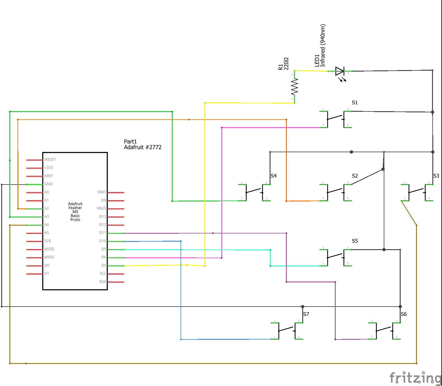
Project Housing/Finishing TouchesTo transfer the project from a breadboard I used some proto board and laid out some taller than average buttons in a similar as the Apple TV remote's buttons. I placed the IR LED at the top of the board and bent it at a 90 degree angle so that it would point straight ahead. I went with a Feather board from Adafruit since it has the m0 chip for Circuit Python, was smaller than a Metro m0 (which I prototyped on) and had enough I/O to support the LED and seven buttons. For power, I'm using two cell batteries in a plastic housing that plugs into the JST terminal on the Feather.
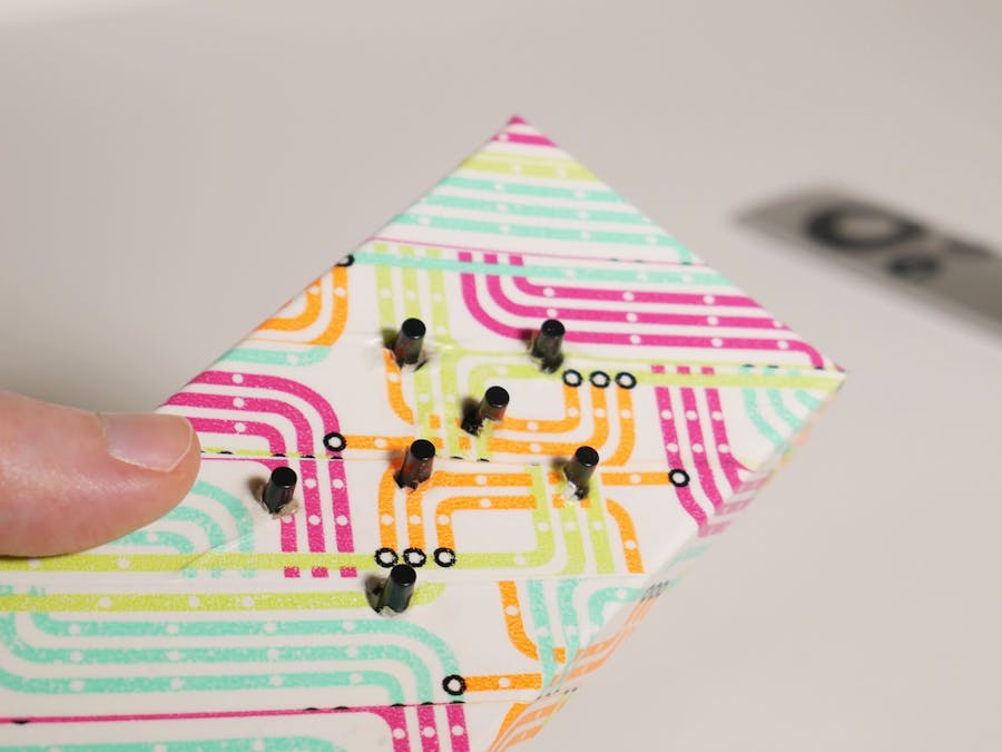
For a housing, I went with a box that a necklace had come in since it was sturdy and had the perfect shape. I poked holes in the lid for the buttons and a larger hole at the front for the LED. I went with the taller buttons so that they could poke through the holes to give a cleaner look. The proto board is sitting on four plastic screws to get the buttons at the right height and the Feather and batteries are hanging out at the other end of the box. For a slightly more finished look I put washi tape over the top of the box. This covered up the torn bits of cardboard from poking the holes and also brightened everything up.
Overall I'm pretty happy with the project. I would like to investigate a bit further into trying to get the Apple TV to recognize the remote without having to sync it, but for now it's great to know I have a fully functioning remote that's much harder to lose. It's also repairable if something happens to it. I'd also like to experiment with other remotes to see if the IR frequencies varied like the Apple TV remote.
I'd also be curious to see if adding a second IR LED would improve the range of the signal and of course, a 3D printed enclosure along with a custom PCB would really tie the whole thing together. The circuit is very simple so it would be a great candidate for it.


Comments
Please log in or sign up to comment.