


Hardware components | ||||||
| × | 1 | ||||
| × | 1 | ||||
| × | 1 | ||||
Hand tools and fabrication machines | ||||||
 |
| |||||
If you prefer video to the written word, you can find a video on this project here.
When you shoot video, you need lights. I quickly learned this after starting my YouTube channel and not being able to always shoot near a window when it's a beautiful sunny day. Video lights are expensive though, so I invested in some surprisingly cheap 160S LED panels from Monoprice (unfortunately it looks like Monoprice does not sell this model any longer ☹). They run on 6 AA batteries (or lithium battery of your choice- I never used one but they list out the compatible ones) which is great until the batteries start to die. After about 3-4 shoots, the batteries would begin to lose their strength and the lights would begin to dim. I'd try to compensate by adjusting the brightness ( a great feature of the lights- especially at the price), but eventually I'd find myself trying to do emergency exposure correction during editing, which often resulting in artifacts or a less than beautiful shot.
SolutionA few months back I did a video, which you can watch here, where I tore down one of these lights to see what the guts looked like and to see if it would be possible to run the light on AC power instead of batteries. I had looked into aftermarket solutions that use "dummy batteries" that are basically plastic or cork cylinders with conductive ends to sit in the battery compartments with a plug to plug into a DC power supply. These are surprisingly expensive (~$70 for 6 dummy cells and a PSU) and making my own wasn't something I was interested in if I was able to just mod the existing light directly rather than working within the battery parameters. I tested by hooking up alligator clips to the power connections on the PCB inside the light that were connected to a 9VDC PSU (6 AA batteries @ 1.5V each = 9V) and it worked without an issue, so I knew a more permanent iteration of this would work.
Step 1Getting into the light is fairly simple. First, pluck out the foam circles in the four corners of the front of the light's frame which are covering four screws that you need to remove.
Next, lift out the silver insert that helps reflect the light and then unscrew the LED PCB, which has four screws in each corner. Be gentle lifting this out since it is connected by two wires (GND & PWR) in opposite corners to the inner power conditioning PCB.
Then you're going to remove both of the inner PCBs. First is the power circuit, which has two small screws, one in the middle and one on the edge. The power circuit has a small plug into the button/status LED PCB to connect the buttons to the power circuit. Unplug it carefully to ensure nothing gets torn. The power circuit is still going to be connected to the battery circuitry so it won't be fully loose from the housing.
Next is the button/status LED PCB which has three screws along the edge. It's also held in with some very sticky double-sided tape that you'll have to wrestle with a bit. This is to keep the surface mounted buttons in place with the rubber button covers which aren't 100% secure. This PCB has an additional small plug connected to the battery tester button. Just like that other plug, unplug it to make sure nothing gets torn. Back to that battery tester button, you'll see a small rectangular piece of plastic on the side where that wire is going. Unscrew the two screws and you'll be able to lift out that wire.
This next part is a bit destructive and should obviously only be done if you never want to use this light with batteries again. I snipped out the battery GND and PWR wires and then bent out the AA battery clips on the inside of the case. Then I went to work on getting the AA battery compartments out. They're just clipped into the outside of the case with plastic clips but they're very snug and require some muscle and patience to get out. First I ran the jimmy from the iFixit tool kit underneath all of the compartments and then mainly used the metal spudger to pry each one out. I tried to get a good angle and pry up to bend it so that I could pull each one out. After that you basically have an empty plastic shell for the light housing.
Now that the clean-up was out of the way it was time for the fun part: the actual mod. I picked up 25 FT of lamp wire on a spool at Lowe's for about $10. I used approximately 12.5 FT for this lamp and will use the remainder for the second lamp that I do this to. I went with lamp wire since it's for lamps and these are, um, lamps. You get two separate stranded copper wires that are shielded together which makes wiring for long distances a breeze.
I snipped away the leftover battery wires leaving a few inches connected to the power circuit PCB since I didn't have a proper way to desolder at the time (working on this). I then soldered together the lamp wire to the former battery power leads and put heat shrink over each connection. Next was the DC female jack, which I snipped out from a cable that had the jack and two alligator clips connected to it. I just snipped the alligator clips and stripped back the outer casing to reveal the GND and PWR wires, which I soldered to the other end of the lamp wire (GND to GND and PWR to PWR of course). I put heat shrink over both connections and then a larger piece over the connections to clean things up since this would be exposed to the wild.
While all of the guts were still out I did a quick test with the 9V PSU and everything was working. Now it was time to get it back into the housing.
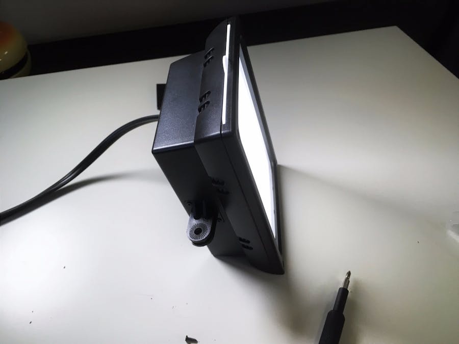
Getting everything back inside was without incident. First I fed the DC female jack out the back of the light followed by most of the lamp wire. I did have to cut away a bit of the plastic housing, which previously had tabs for the batteries, but it cut away pretty easily. I lined the edge of the hole with electrical tape to make sure a rogue piece of jagged plastic didn't harm the wiring. After that, I screwed back in both PCBs and secured the new wiring. I used a zip tie to secure the new bits of lamp wire since it wanted to swim around inside the housing. I didn't plug back in the battery tester button since there were no more batteries to test. Next I got the LED PCB back in, followed by the silver tray and the front frame. Plugging it in for the first time in its finished state was a success. The light was operating battery-free.
I used the light in its AC-powered state for the first time to shoot the talking head portion of the video for its project documentation. Everything worked as expected with no sparks, flames or other malfunctions. I look forward to doing this to a second light so that I can finally stop having battery panic and hopefully have a consistent and higher quality in my videos going forward. One thing to add on the theme of projects like this: be smart when dealing with electricity; especially power supplies. Use common sense. Do your research on the topic in general but also on the specific device that you're attempting to mod. Basically safety first.
Future IdeasOne last thing that I started thinking about during this project was the concept of an open source light panel. The housing would actually be fairly simple to draw up in CAD and then 3D print. The circuit for the actually light is also very simple, you just need the LEDs, power conditioning and then controls. It would be cool to investigate further into the idea of designing a scalable video/photography light solution that people could build themselves using the available resources so that it could fit their needs, either small or large; especially thinking about how expensive these lights can get. But that's a project for another day.


Comments