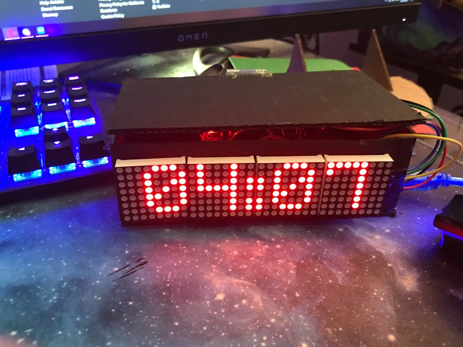
oh my god whaaaat
Yeah, there's not much to say about the finished product.
Let's just move on to the building part.
How to build?First, grab an RTC Module and a Piezo Buzzer.
Connect:
- RTC GND to GND
- RTC VCC to VCC
- RTC SDA to SDA
- RTC SCL to SCL
- Buzzer GND to GND
- Buzzer signal to pin 3
- Buzzer VCC to VCC (i think some require this but mine doesn't)
I chose to use this tiny breadboard to fit all the internals.
Next, grab 4 LED Matrixes.
Next, connect:
- VCC to VCC
- GND to GND
- DIN to Pin 6
- CS to Pin 5
- CLK to Pin 4
Now, this is the part where you can stray away from the guide.
You need to make a case to hold all the circuitry, and an area to hold the screen.
I opted for some cardboard, hot glue, and a random hinge to make mine.
You can do whatever you want though.
And that's the build!
Now, on to using it!
How to use?To get the time working, just plug it in and upload the code.
rtc.adjust(DateTime(F(__DATE__),F(__TIME__)));This line will take care of that for you.
To adjust the alarm time, edit this line:
int ALARMHOUR = 16;
int ALARMMINUTE = 07;
ALARMHOUR is the hour the alarm will go off (NOTE: THIS IS IN 24 HR TIME)
ALARMMINUTE is the minute time.
Ex: HOUR = 13, MINUTE = 23, Alarm will go off at 1:23 PM
I also added an additional debug feature for the alarm.
Typing "a" into the serial monitor will trigger the alarm to go off.
There's also a debugTime() function you can uncomment if you're having issues with the RTC.
And that's the project!Happy building!


_ztBMuBhMHo.jpg?auto=compress%2Cformat&w=48&h=48&fit=fill&bg=ffffff)


Comments
Please log in or sign up to comment.