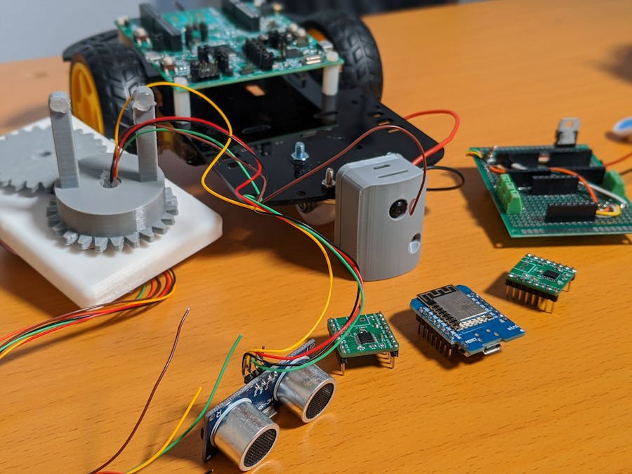
The idea behind the crossover challenge was to write code for the i.MX RT1010 evaluation board and that is the reason why I decided to create an example rover platform that interfaces a couple of peripherals.
The rover maps the surroundings by using an ultrasonic sensor and sends this information over the internet to an APP. This can then be used to create a 2D map of the area in question. The rover can also be controlled remotely over the internet and it also provides a live video feed.
Overview Of The ProjectThe video above gives you a quick overview of the project and can be used as a starting point to understand the project. I also take the rover apart towards the end of the video so that you can view how it was put together. Please check the project links for the source code and the relevant project information.
Some Software Components That Were Used:
- GPIO: Inputs & outputs for ultrasonic sensor interfacing, stepper motor control, obtaining remote control state
- PWM: For DC motor control
- Timers: General time-keeping, capturing the echo signal from the ultrasonic sensor
- UART: To send mapping data to the APP
The image above shows you the different blocks that make up the project. I have tried to simplify everything as best as I could. We will cover the individual section below.
NavigationI decided to use an off the shelf rover frame to demonstrate the project. It uses an acrylic frame along with standard, geared, DC motors. For motor control, I decided to use 4 PWM channels along with a custom motor driver.
The schematic for the motor drivers along with the interfacing diagram is shown above. It uses the DRV8847 motor driver from Texas Instruments which is extremely similar to the DRV8833 motor driver modules that are commonly available.
Since the RT1010 board does not have wireless connectivity, I decided to use a WeMos D1 mini board for remote control. The APP uses a joystick for control and the XY values from this joystick are sent over to the WeMos D1 board. It then processes these values and maps them into 7 different states. These states are then represented as a 3-bit value using the GPIO pins D5, D6 and D7.
The RT1010 board simply reads these GPIO inputs and sets the correct PWM values accordingly. The video goes over the mapping function and also shows you the preprocessor directives that can be updated to suit your requirements.
Mapping:An ultrasonic sensor can be used to obtain the distance from an object in front of it. If you rotate this sensor 360 degrees then you can get an idea of the objects around you and that is exactly what I have done to map the surroundings. The HC-SR04 module was used to obtain this data and a stepper motor was used to rotate and control its position. Since we do not want to twist the wires, a slip ring was used to separate the stationary and rotating sections.
The ultrasonic module that is being used works at 5V which means that we need to take care of voltage conversion. It has a total of 4 pins - 2 for power and 2 for signals. The trigger pin is an input and since a 3.3V signal is sufficient to trigger it, we can directly connect it to the RT1010 board. The echo pin produces a 5V output signal which means that we need to convert this to 3.3V. I decided to use 3x 10K ohm resistors which act as a voltage divider to take care of this conversion.
The same DRV8847 motor driver board was used to interface the stepper motor and I used 5V as the motor voltage. The stepper I was using had internal gears which limited the maximum rotation to about 15RPM. This was suitable for this demonstration and I decided to go with this as I had 3D printed the interlocking gears. It would be advisable to use a faster stepper motor and also use bearings to smoothen the rotation.
Once the mapping data is obtained, it is sent over the debug serial port. This is connected directly to the input of the WeMos D1 board and it is configured such that the data appears over the virtual terminal. This data can then be used to create a 2D map of the surroundings.
Video Feed:The video feed is perhaps the simplest among everything as it uses a standalone board to produce the feed. The ESP32-CAM board was used here and we have covered this in a previous post so please do use the link below to learn more about it:
https://www.hackster.io/BnBe_Club/9-rtsp-video-streamer-using-the-esp32-cam-board-8832b4
In summary, the board simply creates an MJPEG stream that can be accessed over the network. The IP address is then fed into the APP to view the video stream.
Voltage Regulation:I decided to keep things simple and used a 9V battery as the power source. A 7805 voltage regulator was then used to convert this to 5V. You could upgrade this to a LiPo battery to extend the overall battery life. Adding a DC-DC step-down converter will also improve the overall efficiency, depending on your final application.
Source Files:The source code along with the reference files are available for you to use. Please take a look at the links contained below.


Comments
Please log in or sign up to comment.