Arduino Controlled Pinball Machine
Building an Arduino controlled pinball machine required a combination of woodworking, mechanical, electronic and programming skills. It took about six months of part time effort to create and was the most complicated thing I’ve ever built. This is mainly because I was unable to find much information on how to build a pinball machine.
This document will provide a description of how this machine was built. I will try to provide enough references so that if you decide to build your own, you should have an easier time of it than I did. At the same time, I cannot stress enough the need to test everything. I used a spare piece plywood to prototype every component before installing in the actual machine. This will save you a lot of grief in the long run.
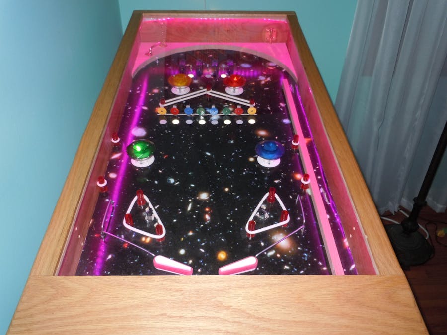
As you can see from the picture, the machine has a wood cabinet and uses commercially available pinball machine replacement parts. The machine is controlled by a single Arduino Mega 2560 board. If you want to see the machine in action, go to this link, or watch here:
The Case
The case is made from oak faced plywood bought at the home store. All the dimensions in this document are in inches. The front and back panels are 20H x 23W. The side panels are 20H x 47L. The pieces were cut with mitered edges and connected using a biscuit joiner and wood glue. Pocket screws and glue would have also worked. The machine is going to take a lot of abuse so it needs to be strong. Before joining it together, I also cut a ¾” dado 1 inch up from the bottom. Do not glue the shelf. It needs to float to allow for expansion and contraction. The shelf was used to hold the main power supply and the power supply for the decorative LED light mounted under the lid. The playing surface is 22w x 42L. Note that it is significantly shorter than the cabinet. This gives me about 3 inches in front to pass wires up to the flipper buttons and to the LED lights. It also gives room for the ball plunger mechanism. The playing surface simply rests on some small wooden blocks screwed to the sides about 4 inches below the top of the case. To get at the guts of the machine, I simply open the lid, remove the playing field and flip it over.
The case and the playing surface are all built at right angles. The pitch of the game is provided by the legs as shown by this side view. Pinball machines can have angles from as little as 1 to up to 7 degrees. The higher the angle the faster the game. Since I wasn’t sure what angle I was going to need, I designed the legs to be adjustable. The legs themselves are wooden and available at most home stores. I then drilled a hole 12 inches deep in the end of each leg using an auger bit. At the bottom end I used to a two component epoxy to insert a 3/8 inch tee nut. Be careful not to get any glue on the threads or where it will block the hole you drilled. I then inserted a 12 inch 3/8 inch thread rod into the leg and I threaded a nut onto the rod. I then attached a leveling foot to the end. The leveling foot and tee nuts I got at the links below.
http://www.mscdirect.com/product/details/40610032
http://www.mscdirect.com/product/details/67300962
Table leg mounting plates were simply screwed to the bottom shelf and the legs screwed in. To adjust the height of the machine, simply loosen the nut and then screw the threaded rod in or out. Then retighten the nut to make sure that the table stays secure.
In the picture, you will notice an electric cord and USB cable. The electric cord comes from a power strip that I attached to the back of the machine. Everything gets plugged in there, so that one switch turns everything on or off. The USB cable is there, so that I can reprogram the Arduino board without having to remove the playing field.
The Lid
The lid frame is made out of oak and is the same out dimension as the cabinet. The top and sides are 1.5 inches wide, while the bottom is 5 inches wide. The extra width on the bottom is used to hide the gap between the playing field and the cabinet. A dado was run down the inner edge of the frame pieces to hold the Plexiglas cover. I used Plexiglas instead of glass because it is lighter, safer and easier to cut. The lid was put together using pocket screws. I did this so that I could take it apart in case the Plexiglas ever needed replacing. I also mounted a strip of colorful LED lights under the lid for decorative purposes. Finally, I mounted the lid to the case using a piano hinge that I recessed into both the lid and the case.
Arduino
The Arduino Mega 2560 basically does four things. It determines when switches are activated, it turns lights on or off accordingly, it keeps track of the scoring, and it displays the score and ball number on a small LCD. Most of the wiring is pretty simple. For example, the targets are connected to one of the Arduino’s digital inputs and to the ground. The input is configured using a statement as shown below.
pinMode(Pin_Number,INPUT_PULLUP)
When the code detects that the input has changed from high to low, it knows that the target has been struck and then turns on the appropriate LED pinball light.
The only complication in this is from the Pop Bumpers. The rollover switches and targets used in this game all get their power from the Arduino. The Pop Bumpers get theirs from a separate 25 volt power supply as they need more juice than the Arduino can supply. The Pop Bumpers do have a switch activates them, but I can’t read it directly because of the high voltage. Consequently, I first send the output from the Pop Bumper switch to a voltage divider. An example of a voltage divider can be found in the link below.
Once through the voltage divider, the voltage is reduced to 5 volts and the Arduino can handle it. I found out that I got less false readings with these if I used the Analog inputs, since the voltage dividers seem to always leak some current. With the Analog inputs, I could check that a threshold was exceeded so that I could easily separate a signal from noise.
During play, if all of a certain type of device (target, pop bumpers, or rollovers) had been activated, I programed the Arduino to flash all the lights for those devices and then increased the scoring for them.
I also used a small force sensor to tell when a ball had been lost. This allows me to keep track of the number of balls played and determine when the game is over. When the game is over, all of the lights flash in sequence.
Finally, I used the Arduino to display the score and ball number.
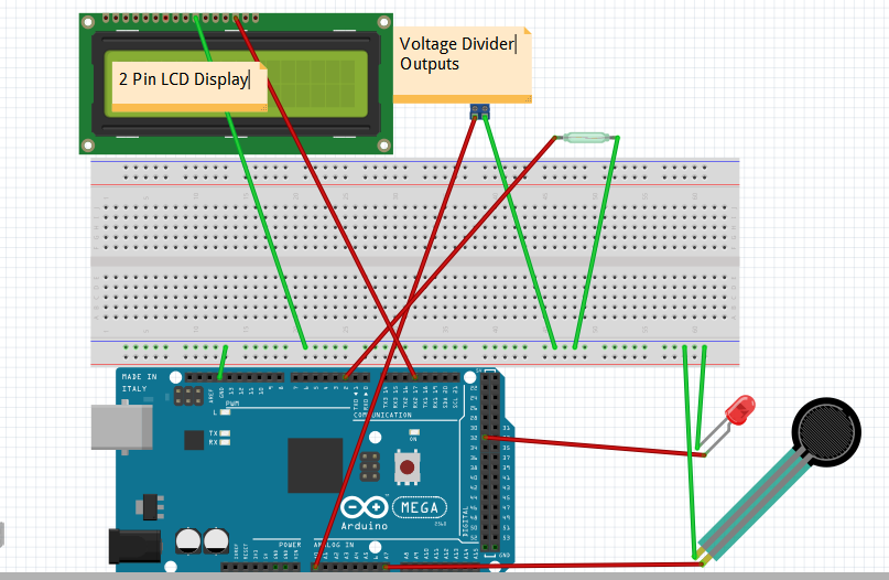
The attached wiring diagram shows how one of each of the major components was wired. The diagram would be too confusing if they were all displayed.
Power Supply
To power the pinball components, I went with a 24 volt power supply. This unit had plenty of power for the flippers and the sidekicks. It is a little weak for the pop bumpers. You may wish to use a stronger power supply for these. If you do, you will have to make your own voltage dividers, since I could only find ones that had a maximum of 25 volts. Information about how to make a voltage divider can be found here.
Rather than connect everything directly to the power supply, I ran wires from it to a pair of bus bars than I mounted onto the underside of the playing field. This made it a lot easier to connect the different components. You can see one of the bus bars in the second picture in the Slingshot section. They are available at the home store in the electrical department.
Ball Shooter or Plunger
The ball shooter or plunger was purchased at the following link
http://www.marcospecialties.com/pinball-parts/B-12445
A hole needs to be drilled through the front of the case for the plunger to pass through. It is then screwed into the inside of the case. Great care has to be done to make sure that the plunger is properly aligned with the playing field. Place a straight edge on the playing field and mark the point where it hits the inside of the case. Then go up enough so that the middle of the plunger is equal in height to half the height of the pinball. (Pinballs are 1 and 1/16 inches in size and are available at Pinball.)
Playing Field
The playing field is made out of ¼ inch birch faced plywood. To make the game more decorative, I bought a picture from the Nasa link below.
http://hubblesite.org/gallery/printshop/ps35/
I first sprayed the plywood with contact adhesive and then laminated the poster onto it. I then turned it over and trimmed it to size.
Flippers
The flippers were purchased at the link below.
http://www.pinballlife.com/index.php?p=product&id=172
When you buy most pinball components, they tend to come with no useful instructions. The way to wire the flippers in shown in the picture below. It came from this link.
In addition to the flipper mechanism, you will need a flipper bat, flipper switch and a button.
Slingshots
A full slingshot assembly can be found here. You will also need pins and the rubber bands. You can find them at the same location. Also shown is a picture of the slingshot when mounted underneath. I should point out that 16 gauge wire was used for all of the components hooked up to the 24 volt power supply and 22 gauge wire was used for the connections to the Arduino board.
The first picture also shows some metal rails next to the flipper bats. I could not find a place to buy the rails, so I made them. I used some chrome steel wire that I found in the home store. It was used to mark lawns when they’ve been sprayed with insecticide. I cut and bent the wire. I then drilled holes in the playing field and epoxied the rails in place.
Pop Bumpers
Pop bumpers assemblies can be purchased here. You will also need switches and caps. Pop bumpers are installed by drilling three holes, two for the metal support rods and one for the shaft that triggers the switch. When a ball rolls into the white disk seen on the top view, it pushes the shaft down. This triggers the leaf switch, which then activates the solenoid. The solenoid then pulls a metal ring down that sends the ball in the opposite direction.
Targets, rollover switches and lights
The targets are available at the link below.
http://www.marcospecialties.com/pinball-parts/A-14691-5
Rollover switches and mounts can be found below.
http://www.actionpinball.com/parts.php?item=A-12687
The lamps that I used are no longer made, but equivalents are shown below.
http://www.actionpinball.com/parts.php?item=LED4555
You will also need the lamp mounts shown below.
http://www.actionpinball.com/parts.php?item=077-5030-00
Wiring of all of these is basically the same and was mentioned in the Arduino section.
Summary
Once you get started, you will no doubt find other bells and whistles that you will want to add, but this should get you started.


_wzec989qrF.jpg?auto=compress%2Cformat&w=48&h=48&fit=fill&bg=ffffff)


Comments
Please log in or sign up to comment.