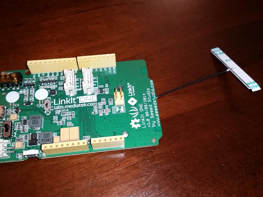
The Wireless Environment Station for Internet of Things is a central hub using the LinkIt One board that provides environmental feedback available to networked devices.
The WES hub has several sensors connected locally. It utilizes the battery pack and WIFI antenna to host a webpage even when power is unavailable. The webpage can be access by any networked device and contains all of the available sensor data. Using this, smart devices within your home can make decisions based on the feedback they read from the webpage.
I've setup my LinkIt One board on a breadboard so I could easily move the hub around, but you can easily use wires or shields to connect different sensors. Setup your hub with the sensors you'd like. I've used two I2C and an analog sensors in this example.
You'll also need to setup your SD card to contain the SSID and password of the WiFi network you'll want to use. The SD card should be formatted as FAT and should contain a file named "wifi.txt". You can add additional files to the SD card for future additions if you'd like. The WiFi file should contain two lines of text as follows:
WIFI_AP YOUR_SSID
WIFI_PASSWORD  YOUR_PASSWORD
Where YOUR_SSID and YOUR_PASSWORD should be changed to your personal settings. I've attached a template file here.
Download the project folder from the linked GitHub repository.
There are libraries included in the "Files" directory for the sensors used in the example. If you're planning to use the sensors I've used and the project I've included, you'll want to move these to your library directory first.
You can copy the Template.ino project and follow the comment blocks for adding new sensors. You can also view my example version in Gaia.ino.
Make sure you have setup your LinkItOne board correctly. You can view the position of my switches here.
Once you've got your hardware and software together you can check that your hub is properly initializing and connecting to your network. Open the Serial Monitor and you should see output similar to the following where XXX is the local IP of your device:
- Starting initialization
- Initializing SD card
- Reading
wifi.txt
- SD card initialization complete
- Initializing sensors
- Sensor initialization complete
- Initializing WiFi
- Connecting to AP
- SSID: GGGI2
- IP Address:
192.168.1.XXX
- Subnet mask:
255.255.255.0
- gateway IP:
192.168.1.1
- signal strength (RSSI):
-65 dBm
- Wifi initialization complete
- Initializing Server
- Server initialization complete
- Initialization complete
Once everything is up and running you can access the webpage by connecting to the same WiFi network and entering the IP Address of your device in the address bar. Your device will return a webpage that contains either individual tags containing the sensor information, HTML text containing the sensor information, or both. This can be configured by commenting or uncommenting the following tags at the top of the project file:
#define PRINT_HTML_TAGS
#define PRINT_HTML_TEXT
The webpage from the example project would show something like:
From here, other internet enabled devices could parse the data and make decisions based on it.
Thank YouThank you for taking the time to view my project. I hope you are able to build on the work I've started here. Please feel free to leave any questions or comments.


_3u05Tpwasz.png?auto=compress%2Cformat&w=40&h=40&fit=fillmax&bg=fff&dpr=2)
Comments