


Hardware components | ||||||
_ztBMuBhMHo.jpg?auto=compress%2Cformat&w=48&h=48&fit=fill&bg=ffffff) |
| × | 1 | |||
 |
| × | 1 | |||
 |
| × | 1 | |||
 |
| × | 1 | |||
| × | 1 | ||||
 |
| × | 1 | |||
 |
| × | 3 | |||
 |
| × | 1 | |||
An optical chopper is a device that periodically interrupts an external beam of light. While a few different types of optical beam choppers are used in science labs, this is similar to an optical shutter, which periodically opens and closes to allow light to pass at defined intervals. Choppers of this type enable a consistent and reproducible dark vs. light comparison in many types of experiments, such as photoelectrochemistry. For a brief example of one type of experiment that utilizes an optical chopper, consider the photocurrent density measurements conducted on Iron(III) Oxide decorated with Pt or CoPi (https://openi.nlm.nih.gov/detailedresult.php?img=PMC3775410_srep02681-f3&req=4). In the figure at the right, there is a clear increase in photocurrent when illuminated with light compared to the current density in the dark. An optical chopper enables this type of comparison.
The Simple Arduino Optical Chopper is essentially an optical shutter that operates by blocking the light beam with a servo arm (10 degrees) and unblocking the light beam (90 degrees) at a set interval. This is a task that I previously accomplished (frustratingly so) by using a piece of paper or cardboard and manually blocking the beam of light while closely monitoring a stopwatch. Using an arduino and servo motor allows for a more reproducible experiment and more consistent chopping interval than doing so manually. And best of all, I don't have to stand next to the experiment the entire time.
General Operation
The chopper program is initiated by pressing the button switch one time. The program consists of two phases: quiet time and beam chopping. The amount of quiet time is specified by the variable quietTime and can be used to allow for an extended period of "dark" at the beginning of an experiment (e.g. to allow the current density to reach a baseline in a photoelectrochemical experiment). At the end of quiet time, the chopping phase begins for the remainder of the total time (specified by variable totalTime) and the servo motor alternates between the closed and open angles at a time interval specified by the variable chopInterval.
When the total time is reached, the program ends and the servo arm is returned to the closed angle. The running program can be stopped at any time by pressing the button switch once, which sets the servo motor to the specified closed angle. The arduino's onboard LED 13 is used to monitor if the program is currently running.
This project is broken up into two sections, the first demonstrates how to built a bare-bones version of the simple optical chopper and the second adds features like and LCD to view the specified time intervals and potentiometers to manipulate those intervals without changing them in the code. You can read through the tutorial or find the schematics and code for both section in the attachments.
The Simple Optical Chopper
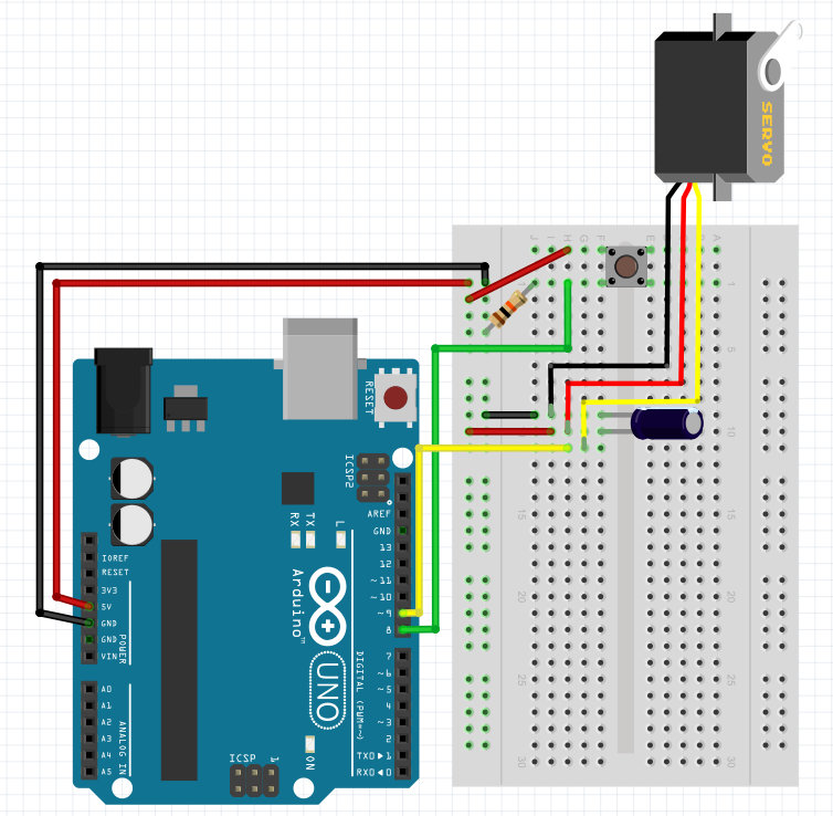
This section will describe how to build and code the bare minimum necessary for an optical chopper. This chopper consists of three main components: a servo, which physically does the chopping; a tactile button, which starts and stops the chop program; and the arduino, which handles the logic between the two.
To start, wire the servo motor to the breadboard and arduino according to Figure 2. Note that my particular servo does not match the Fritzing wiring diagram, so pay close attention to the pin-out on yours. Include a decoupling capacitor that bridges the 5V and GND pins of the servo. When a servo motor begins to move, it draws a larger current than it would if it were already in motion, causing a drop in voltage on the board. Double check that the cathode of the capacitor is connected to ground.
The Simple Optical Chopper Code
Before the setup function, we must include the servo library and variables to keep track of the run time and chopping interval. Here, I have set the quiet time, chop interval, and total time to 2 min, 4 s, and 4 min, respectively. Essentially, we want the program to run with the chopper closed for 2 minutes and then begin chopping, switching between open and closed every 4 seconds until reaching a total run time of 4 minutes. These were the best values for my application, but obviously feel free to modify them for yours.
#include <Servo.h>
Servo myServo;
unsigned long quietTime = 120000;
unsigned long chopInterval = 4000;
unsigned long totalTime = 240000;
The next set of variables will store different states of the program (e.g. whether or not the chop program is running, if the switch is being pressed, the elapsed time, etc.)
// variable used to indicate that the chop program is running
// value of 1 or true means program is running
int programRunning = 0;
// previous state of the start button
int previousSwitchState = 0;
// start button input pin
const int startButtonPin = 8;
// onboard LED used to indicate that chop program is running
const int ledPin = 13;
// time of previous interval
unsigned long previousMillis = 0;
// time that the start button was pressed
unsigned long programStartTime = 0;
// servo angles for both open and closed positions
const int closedAngle = 10;
const int openAngle = 90;
The optical chopper will operate in two different "states," running and not running. The tactile button switch will allows us to alternate between the two and the current state will be stored in the variable: programRunning.
The next variable is a little bit less intuitive. Since the arduino's loop function runs thousands of times per second and we cannot possibly press the button for one program cycle, it is best to monitor for a change from a LOW to HIGH signal on the pin connected to the button, hence we will compare the previousSwitchState with the current button state later in the code.
The button will be connected to pin 8 and we will use LED 13 as an on-board visual indicator that the chop program is running.
Because the chop program relies heavily on time intervals, we must keep track of both: when the start button was pressed and how long it's been since the previous change in servo position. To do that, we define previousMillis and programStartTime.
Finally, we define the servo angles that correspond to open and closed (i.e. light beam is unblocked, or light beam is blocked). 90 and 10 degrees worked best for the servo I used.
Lets look at the setup function now:
void setup() {
  // pin 8, the start button is an input
  pinMode(startButtonPin, INPUT);
  // pin 13, the program running indicator LED is an output
  pinMode(ledPin, OUTPUT);
  // servo is attached to pin 9
  myServo.attach(9);
  // console for diagnostics
  //Serial.begin(9600)
}
Nothing too complex here. The start button is wired to pin 8, we use pin 13 as an indicator that the chop program is running (otherwise it might be hard to tell during quiet time and these tactile button switched are easy to accidentally press twice), and we are dictating the position of the servo via pin 9. Finally, I included the Serial.begin() function in a comment, which is useful for troubleshooting.
Now let's work on the meat of the code, the loop function:
void loop() {
  // gets the current runtime in milliseconds
  unsigned long currentMillis = millis();
  // reads the start button switch state
  int switchState = digitalRead(startButtonPin);
}
To start each run through the loop, we will want to keep track of the current time according to the arduino's internal clock and whether or not the switch is being pressed.
Next let's code the behavior for the start button,
// start/stop button
if (switchState != previousSwitchState) {
  if (switchState == HIGH) {
    programStartTime = currentMillis;
    programRunning = !programRunning;
  }
}
Since we check the state of the switch each iteration through the loop, we can compare it to the state of the switch during the previous iteration, looking for that change from LOW to HIGH when it is initially presses. NOTE: we will assign the value of previousSwitchState to currentSwitchState at the end of the loop in order to make a meaningful comparison on the next iteration.
If there is a change in the switch state from LOW to HIGH, the start time is assigned to the current time and the value of programRunning is switched.
Next, we will address the behavior when the chop program is running (programRunning is true).
// if the program running state is true as a result of pressing the start button
if (programRunning) {
  //turn the program running indicator LED on
  digitalWrite(ledPin, HIGH);
  // if quiet time has passed and total time has not been exceeded
  if (currentMillis >= programStartTime + quietTime) {
    // if the current time is still less than the total run time
    if (currentMillis <= totalTime + programStartTime) {
      // if the interval time has passed
      if (currentMillis - previousMillis >= chopInterval) {
        // stores the current time as previous time
        // switches the state of the servo motor
      }
    }
  }
}
There are a few of different things that our program will do once the chop program begins running: count down the specified quiet time, decide when the servo should allow the beam of light to pass, determine when the program should end. The nested conditionals contain the requirements that must be met in order to open the servo. First, quiet time must have ended; second, the program must not have exceeded the specified total run time; and finally, the defined chop interval must have passed.
If all of these conditions are met, we check the position of the servo, and if it is at the closed angle, we have it switch open by adding the following code to the inner most conditional above:
// stores the current time as previous time
previousMillis = currentMillis;
if (myServo.read() == closedAngle) {
  myServo.write(openAngle);
} else {
  myServo.write(closedAngle);
}
We also want to assign our previousMillis variable, the one we use to determine if the chop interval has been exceeded, to the current time.
But what if the chop interval has not passed? Or if quiet time has not finished? How do we want the optical chopper to behave?
Looking at each conditional, if quiet time has not finished, the servo should remain at its closed angle. If we have exceeded the total run time of the program (i.e. the program has just ended), the servo should be at its closed angle and we should change the value of the programRunning variable to false. Finally, if the chop program is not running, we want the indicator LED (13) off and the servo moved to the closed position. We can accomplish this be filling in the following else statements:
// if the program running state is true as a result of pressing the start button
if (programRunning) {
  //turn the program running indicator LED on
  digitalWrite(ledPin, HIGH);
  // if quiet time has passed and total time has not been exceeded
  if (currentMillis >= programStartTime + quietTime) {
    // if the current time is still less than the total run time
    if (currentMillis <= totalTime + programStartTime) {
      // if the interval time has passed
      if (currentMillis - previousMillis >= chopInterval) {
        // stores the current time as previous time
        previousMillis = currentMillis;
        if (myServo.read() == closedAngle) {
          myServo.write(openAngle);
        } else {
          myServo.write(closedAngle);
        }
      }
      // the servo returns to original position and the program is stopped
      // when total run time is reached
    } else {
      myServo.write(closedAngle);
      programRunning = !programRunning;
    }
  // servo remains in original position if still in quiet time
  } else {
    myServo.write(closedAngle);
  }
// servo remains in original position when chopper program is not running
} else {
  digitalWrite(ledPin, LOW);
  myServo.write(closedAngle);
}
This is the heart of the optical chopper code. There is one last line we need to include and it pertains to the start/stop button. We need to include,
previousSwitchState = switchState;
which allows us to monitor for a button press as described previously by storing it and comparing it to the value of switchState on the next iteration through the loop.
That's it! That's all you need for a basic optical chopper! Read on to add an LCD display and the ability to read and modify the chop interval, run time, and quiet time on the fly...
The Optical Chopper with LCD and Potentiometers
The basic optical chopper adds consistency to your photochemical applications, but it would be more convenient to be able to change the timing on the fly and read the amount of time left in the chop program instead of having to go into the code. We will add this functionality with an LCD and a series of potentiometers.
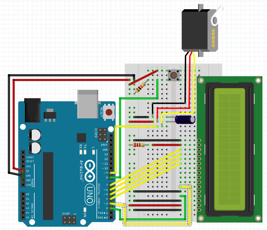
To begin, attach the LCD screen and wire it up as shown in figures 3 and 4. If you are interested in why it requires so many wires, check out the adafruit lcd tutorial.
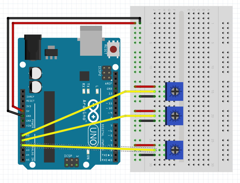
Ultimately, we will be able to view the time left in the chop program in real time. But that's not all... By adding a series of potentiometers, we will be able to adjust the length of the quiet time, the program run time, and the chop interval with just a turn of a knob (or a phillips head screwdriver if you have the same pots as I do). Therefore, the next step is to add the potentiometers and wire them up as shown below:
At this point, your chopper should look something like this:
Now that it's all wired up, lets modify our previous code to accommodate the new features.
The Code for the Optical Chopper with LCD and Potentiometers
We will start with the pots first, but it's a good idea to go ahead and add the arduino LCD library to the top of our arduino code,
#include <LiquidCrystal.h>
Also, we need to tell the arduino how we are connected to the LCD (i.e. which pins). Add this line right under the call to the LCD library,
LiquidCrystal lcd(2, 3, 4, 5, 6, 7);
Alright, let's handle the potentiometers. Since we're going to be changing the values of the variables, quietTime, chopInterval, and totalTime based on the variable resistance of the potentiometers, let's remove the values we gave them previously. Also, I've added another variable, programTime, which will store the length of time that the chop program runs after the quiet time ends. Controlling this time with a pot is more intuitive than the total time. Your code should now look something like this:
// include the servo library and assign to myServo
#include <Servo.h>
Servo myServo;
#include <LiquidCrystal.h>
LiquidCrystal lcd(2, 3, 4, 5, 6, 7);
// quiet time, chop interval, and run time defined in milliseconds
unsigned long quietTime;
unsigned long chopInterval;
unsigned long programTime;
unsigned long totalTime;
Additionally, we need to assign the analog input pins to a variable that indicates what the attached potentiometers are modifying:
// pin assignments for the potentiometers
int const chopIntervalPin(A0);
int const programTimePin(A1);
int const quietTimePin(A2);
That's it for variables. The next code modification takes place when the chop program is not running. While the chop program is not running, we want the arduino to be transforming the analog values from the potentiometers into milliseconds to be used for quietTime, programTime, and chopInterval. Take a look at what we have added to the else condition.
// if the program running state is true as a result of pressing the start button
if (programRunning) {
 // do all that stuff we described previously
} else {
  digitalWrite(ledPin, LOW);
  myServo.write(closedAngle);
  // the potentiometers that manipulate the time variables
  // quiet time between 0 and 300 seconds
  quietTime = analogRead(quietTimePin);
  quietTime = map(quietTime, 0, 1023, 0, 10);
  quietTime *= 30000;
  // chop time between 0 and 300 seconds
  programTime = analogRead(programTimePin);
  programTime = map(programTime, 0, 1023, 1, 10);
  programTime *= 30000;
  // chop interval between 1 and 10 seconds
  chopInterval = analogRead(chopIntervalPin);
  chopInterval = map(chopInterval, 0, 1023, 1, 10);
  chopInterval *= 1000;
  totalTime = quietTime + programTime;
}
The map function is perfect for transforming the analog values from the raw 0 to 1023 range to 1 to 10 "increments." By multiplying these values by a millisecond value, we are defining the magnitude of the increment for each potentiometer (e.g. 30s for quietTime and programTime, and 1s for chopInterval). I found that this approach worked best because mapping directly to milliseconds (e.g. 0 to 300000) lead to difficulty in setting the potentiometer to a precise time such as exactly 4 minutes or 2 seconds. Conversely, this approach gives us nice and easy time increments to work with.
Being able to change the time values in between experiments means nothing if we don't know what we are changing them to. In this section, we will add the code for the LCD.
We have already added the LCD library and told the arduino which pins to use to communicate with the LCD, but we need to add the,
lcd.begin(16, 2);
command to the setup function, which initiates the display and tells the arduino how large the display is.
Similar to the chop program itself, we want to program the LCD to operate in two states: "on" and "off." When the chop program is running, we want the LCD to display how much quiet time or chopping time is left. To do this, I've added two conditionals, one that will display the remaining quiet time and one that will display the remaining chop time:
if (programRunning) {
  digitalWrite(ledPin, HIGH);
  if ((currentMillis - programStartTime) % 500 == 0) {
    // if quiet time has passed and total time has not been exceeded
    if (currentMillis >= programStartTime + quietTime) {
      lcd.clear();
      lcd.print("Quiet Time:");
      lcd.setCursor(12, 0);
      lcd.print((quietTime - (currentMillis - programStartTime)) / 1000);
    }
  }
}
Originally, I found that the LCD was refreshing way to quickly making it difficult to read, thus I added the,
if ((currentMillis - programStartTime) % 500 == 0)
conditional so that the display was only updated twice per second. When refreshed, the LCD clears its display, prints either "Quiet Time:" or "Run Time:", moves its cursor and prints the remaining time in seconds (rounding down to the nearest whole second I believe).
When the chop program is stopped, we want the LCD to dynamically display the values for the chop interval, quiet time, and total run time as well as a "Program Stopped" message.
After we calculate the values from the potentiometers, we can add this code:
if (currentMillis % 500 == 0) {
  lcd.clear();
  lcd.print("Program Stopped");
  lcd.setCursor(0, 1);
  lcd.print("Q:");
  lcd.print(quietTime / 1000);
  lcd.print(" R:");
  lcd.print(programTime / 1000);
  lcd.print(" I:");
  lcd.print(chopInterval / 1000);
}
Similar to the above, this clears the display and reveals the values of the quietTime, programTime, and chopInterval variables as they are changed.
At this point, you should have a display that works something like this,
That's it! All that remains now is to attach a piece of cardboard or something similar to the servo motor, mount the motor to a ring stand, start your experiment, and forget about ever chopping the beam manually again!
I hope you enjoyed this tutorial!


_3u05Tpwasz.png?auto=compress%2Cformat&w=40&h=40&fit=fillmax&bg=fff&dpr=2)
Comments
Please log in or sign up to comment.