


Hardware components | ||||||
_ztBMuBhMHo.jpg?auto=compress%2Cformat&w=48&h=48&fit=fill&bg=ffffff) |
| × | 1 | |||
 |
| × | 1 | |||
 |
| × | 1 | |||
 |
| × | 1 | |||
 |
| × | 1 | |||
 |
| × | 1 | |||
Software apps and online services | ||||||
 |
| |||||
In this project, I will tell you how to build a Home Automation with GSM SIM800L DTMF & Voice Feedback Using Arduino Uno Board
Mobile phone is a revolutionary invention of the century. It was primarily designed for making and receiving calls & text messages, but it has become the whole world after the Smart phone comes into the picture. In this project we are building a home automation system, where one can control the home appliances, using the simple GSM based phone, just by sending SMS through his phone. In this project, no Smart phone is needed, just the old GSM phone will work to switch ON and OFF any home electronic appliances, from anywhere.
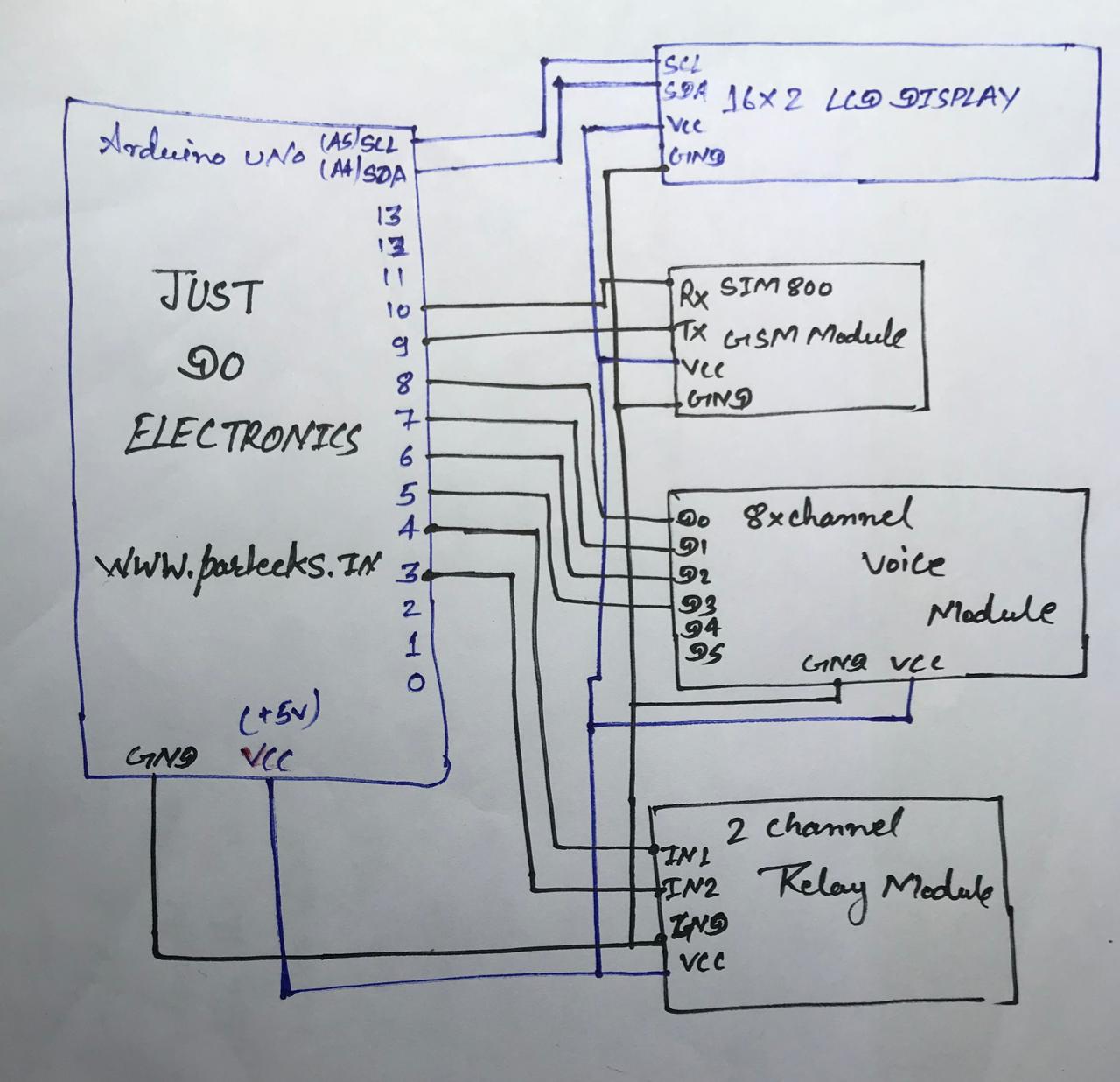
Working ExplanationIn this project, Arduino is used for controlling whole the process. Here we have used GSM wireless communication for controlling home appliances. We send some commands like “#A.light on*”, “#A.light off*” and so on for controlling AC home appliances. After receiving given commands by Arduino through GSM, Arduino send signal to relays, to switch ON or OFF the home appliances using a relay driver.
Circuit
Here we have used a prefix in command string that is “#A.”. This prefix is used to identify that the main command is coming next to it and * at the end of string indicates that message has been ended.
When we send SMS to GSM module by Mobile, then GSM receives that SMS and sends it to Arduino. Now Arduino reads this SMS and extract main command from the received string and stores in a variable. After this, Arduino compare this string with predefined string. If match occurred then Arduino sends signal to relay via relay driver for turning ON and OFF the home appliances. And relative result also prints on 16x2 LCD by using appropriate commands.
Here in this project we have used 3 zero watt bulb for demonstration which indicates Fan, Light and TV.
Below is the list of messages which we send via SMS, to turn On and Off the Fan, Light and TV:
GSM module
This is the GSM module that I will be using in the GSM Alarm System project, in the market we have different types of GSM modules, the one I will be using today is sim900A, the same code is also tested on sim900D, so if you want you can also use sim900A.
Circuit & Code
//Daini

#include <LiquidCrystal_I2C.h>
#include <Wire.h>
LiquidCrystal_I2C lcd(0x27, 16, 2);
#include <SoftwareSerial.h>
#include "Talkie.h"
#include "Vocab_US_Large.h"
#include "Vocab_Special.h"
Talkie voice;

# define GSM_RX 10
# define GSM_TX 9


int P_E = 8;
int P_EE = 7;
int P_EEE = 4;
int P_EEEE = 11;

# define LIGHT1 5
# define LIGHT2 6
# define LIGHT3 12
# define LIGHT4 13
SoftwareSerial gsm_board(GSM_RX,GSM_TX);
boolean call_flag=0, relay_flag=0;
int i=0,j=0,x=-1;
char n[3];
void gsm_initilaize();
void relay();

void setup()
{

lcd.begin(16, 2);
gsm_board.begin(9600);
Serial.begin(9600);
lcd.init();
  lcd.backlight();
  lcd.setCursor(0, 0);

pinMode(P_E, OUTPUT);
pinMode(P_EE, OUTPUT);
pinMode(P_EEE, OUTPUT);
pinMode(P_EEEE, OUTPUT);

pinMode(LIGHT1,OUTPUT);
pinMode(LIGHT2,OUTPUT);
pinMode(LIGHT3,OUTPUT);
pinMode(LIGHT4,OUTPUT);

digitalWrite(P_E,HIGH);
digitalWrite(P_EE,HIGH);
digitalWrite(P_EEE,HIGH);
digitalWrite(P_EEEE,HIGH);

digitalWrite(LIGHT1,HIGH);delay(1000);
digitalWrite(LIGHT2,HIGH);delay(1000);
digitalWrite(LIGHT3,HIGH);delay(1000);
digitalWrite(LIGHT4,HIGH);delay(1000);


lcd.print("IVRS Based Home");
lcd.setCursor(0,1);
lcd.print("Automation With");
delay (2000);

lcd.clear();
lcd.setCursor(0,0);
lcd.print("Immediate Voice ");
lcd.setCursor(0,1);
lcd.print("& SMS Feedback");
delay (2000);
lcd.clear();
lcd.setCursor(0,0);
lcd.print("Using Arduino ");
lcd.setCursor(0,1);
lcd.print("SIM800L DTMF");
delay (2000);
lcd.clear();

gsm_initilaize();
lcd.clear();
lcd.setCursor(0,0);
lcd.print("GSM TEST OK");
delay (2000);
lcd.clear();
lcd.setCursor(0,0);
lcd.print("CALL TO SIM");
}

void loop()
{

{
digitalWrite(P_EEEE,LOW);
digitalWrite(P_EEEE,HIGH);
}
String gsm_data;
while(gsm_board.available())


{
char c=gsm_board.read();
gsm_data+=c;
delay(10);
}
if(!call_flag)
{
x=gsm_data.indexOf("RING");
if(x>-1)
{
delay(5000);
gsm_board.println("ATA");
Serial.println("ATA");
delay(1000);voice.say(sp2_ONE);voice.say(sp4_LIGHT);voice.say(sp2_ONE);voice.say(sp2_ON);
delay(1000);voice.say(sp2_TWO);voice.say(sp4_LIGHT);voice.say(sp2_ONE);voice.say(sp2_OFF);
delay(1000);voice.say(sp2_THREE);voice.say(sp4_LIGHT);voice.say(sp2_TWO);voice.say(sp2_ON);
delay(1000);voice.say(sp2_FOUR);voice.say(sp4_LIGHT);voice.say(sp2_TWO);voice.say(sp2_OFF);
delay(1000);voice.say(sp2_FIVE);voice.say(sp4_LIGHT);voice.say(sp2_THREE);voice.say(sp2_ON);
delay(1000);voice.say(sp2_SIX);voice.say(sp4_LIGHT);voice.say(sp2_THREE);voice.say(sp2_OFF);
delay(1000);voice.say(sp2_SEVEN);voice.say(sp4_LIGHT);voice.say(sp2_FOUR);voice.say(sp2_ON);
delay(1000);voice.say(sp2_EIGHT);voice.say(sp4_LIGHT);voice.say(sp2_FOUR);voice.say(sp2_OFF);
call_flag=1;
}
}

if(call_flag)
{
x=gsm_data.indexOf("DTMF");
if(x>-1)
{
n[j]=gsm_data[x+6];
Serial.println(n[j]);
relay_flag=1;
}
x=gsm_data.indexOf("NO CARRIER");
if(x>-1)
{
gsm_board.println("ATH");
relay_flag=1;
call_flag=0;
j=0;
}
}
if(relay_flag)
{
relay();
}
}

void gsm_initilaize()
{
boolean gsm_Ready=1;
Serial.println("initializing GSM module");
while(gsm_Ready>0)
{
gsm_board.println("AT");
Serial.println("AT");
while(gsm_board.available())
{
if(gsm_board.find("OK")>0)
gsm_Ready=0;
}
delay(2000);
}
Serial.println("AT READY");

boolean ntw_Ready=1;
Serial.println("finding network");
while(ntw_Ready>0)
{
gsm_board.println("AT+CPIN?");
Serial.println("AT+CPIN?");
while(gsm_board.available())
{
if(gsm_board.find("+CPIN: READY")>0)
ntw_Ready=0;
}
delay(2000);
}
 Serial.println("NTW READY");

boolean DTMF_Ready=1;
Serial.println("turning DTMF ON");
while(DTMF_Ready>0)
{
gsm_board.println("AT+DDET=1");
Serial.println("AT+DDET=1");
while(gsm_board.available())
{
if(gsm_board.find("OK")>0)
DTMF_Ready=0;
}
delay(2000);
}
Serial.println("DTMF READY");
}

void relay()
{

if(n[0]=='1')
{
digitalWrite(LIGHT1,LOW);
digitalWrite(P_E,LOW);
digitalWrite(P_E,HIGH);

Serial.println("LIGHT1 ON");lcd.clear();lcd.setCursor(0,0);lcd.print("LIGHT1 ON");lcd.clear();
lcd.setCursor(0,0);lcd.print("PRESS BUTTON");lcd.setCursor(5,1);lcd.print("LIGHT1 ON");
}

else if(n[0]=='2')
{
digitalWrite(LIGHT1,HIGH);

digitalWrite(P_EE,LOW);
digitalWrite(P_EE,HIGH);

Serial.println("LIGHT1 OFF");lcd.clear();lcd.setCursor(0,0);lcd.print("LIGHT1 OFF");lcd.clear();
lcd.setCursor(0,0);lcd.print("PRESS BUTTON");lcd.setCursor(5,1);lcd.print("LIGHT1 OFF");
}

if(n[0]=='3')
{
digitalWrite(LIGHT2,LOW);

digitalWrite(P_EEE,LOW);
digitalWrite(P_EEE,HIGH);

Serial.println("LIGHT2 ON");lcd.clear();lcd.setCursor(0,0);lcd.print("LIGHT2 ON");lcd.clear();
lcd.setCursor(0,0);lcd.print("PRESS BUTTON");lcd.setCursor(5,1);lcd.print("LIGHT2 ON");
}

else if(n[0]=='4')
{
digitalWrite(LIGHT2,HIGH);

digitalWrite(P_EEEE,LOW);
digitalWrite(P_EEEE,HIGH);

Serial.println("LIGHT2 OFF");lcd.clear();lcd.setCursor(0,0);lcd.print("LIGHT2 OFF");lcd.clear();
lcd.setCursor(0,0);lcd.print("PRESS BUTTON");lcd.setCursor(5,1);lcd.print("LIGHT2 OFF");
}
relay_flag=0;
}
NextDFM Software From NextPCB
A PCB Design Problems Detector, An Engineering Solution ProviderImport the Gerber file with one click. No need for complicated file reading steps to review easily and improve efficiency.
Help you quickly familiarize DFM design specifications and production needs to determine whether there are any manufacturing constraints
Features
Make PCB design more standard Prevent the quality flaw
Impedance calculation function and lamination automation
Automatically generate the best puzzle
CAM350 free alternative version
Check Gerber files anytime, anywhere and parse it with one click
Instate Quote and evaluate delivery time Reduce cost and improve benefit
these are advantage comparing to Eagle and Altium।


Comments