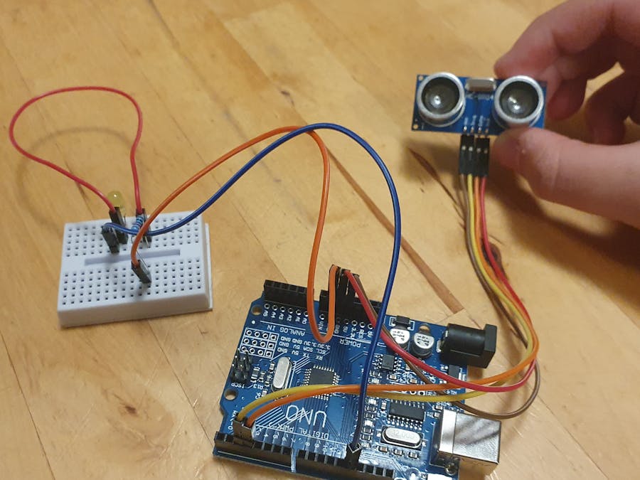
This project was inspired by the recent events of the Covid-19 pandemic, where I figured that I could make a sensor regulating social distancing.
How does it Work? -It works by the ultrasonic sensor sending out high and low pulses to measure the distance between it and an obstacle or person. This is done from converting the time it took for the pulse to come back to a distance (cm in this case).
After the distance is measured, I have coded the LED to turn on if less than 50 cm away (this amount is easily adjustable by changing the value on the IF statement) and turn off when more than 50 cm away. Here is a video showing how it performs.
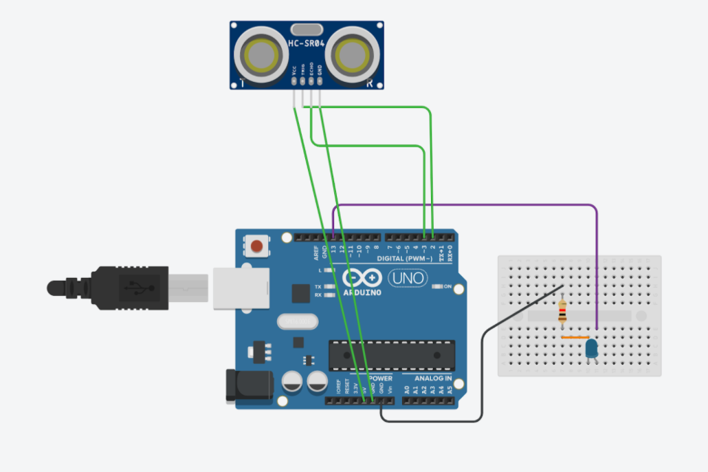
The making of the circuit -At first, I was planning to attach all components to the breadboard of my circuit and not to the Arduino itself but after some testing, I realized it was much easier attaching the ultrasonic sensor to the Arduino while attaching the LED to the breadboard. This way I could also make some space for the LED itself because the ultrasonic sensor would have taken up the majority of the space of the breadboard mini.
The making of the code -First I developed pseudocode and flowcharts to visualize my code and how it would work. This helped a lot in developing the structure and sequencing of the code. After a few adjustments, this was my final flowchart.
After planning the code, I was easily able to make progress in coding the LED but was stuck on developing the code for the ultrasonic sensor as this was the first time I coded something like this.
The ultrasonic sensor works by sending out sound waves that would bounce back from an object that it hits back into the sensor. To utilize this into a social distancing sensor I would have to convert the time it took for the pulse to bounce back into a measurement of centimeters. I achieved this process by using this process.
After some research, I had discovered that for the ultrasonic sensor to work from the code, it would have to program it to fire a low, high, and low pulse. This was to produce a clean pulse from the high pulse. After figuring out the corresponding pins for the echo and trig components of the sensor, I was ready to code an IF statement to turn on the LED when there was an object withing a 50 cm reach. This was definitely the easiest part of the code.
Making of the Casing -Next, I developed the case as a 3D model using the SketchUp software. Unfortunately at this time, I did not have access to 3d printers so I wasn't able to make it but I have attached the 3d printable file above the circuit schematic, if you would like to try it out.


_ztBMuBhMHo.jpg?auto=compress%2Cformat&w=48&h=48&fit=fill&bg=ffffff)


_3u05Tpwasz.png?auto=compress%2Cformat&w=40&h=40&fit=fillmax&bg=fff&dpr=2)
Comments
Please log in or sign up to comment.