

Hardware components | ||||||
 |
| × | 1 | |||
| × | 1 | ||||
| × | 1 | ||||
| × | 1 | ||||
Software apps and online services | ||||||
| ||||||
Hand tools and fabrication machines | ||||||
| ||||||
I added reactive lights to my longboard. A longboard is a skateboard for slow old dudes like me. I was watching the kids skate down the street and disappear into the darkness one night, and it occurred to me that I should stick some lights on them. The skateboards, not the kids. Kids aren't conductive enough for the candlepower I wanted to throw at the effort. I'll take you through the What and How of the project, hopefully you can extend it and make something cool of your own.
The WhatI know, love, and frequently (ab)use PSoCs, and for this project I chose to target a Prototyping module for the PSoC4. Plenty of resources, and small enough to attach to the board. Groovy!
Product page for the Proto Module.
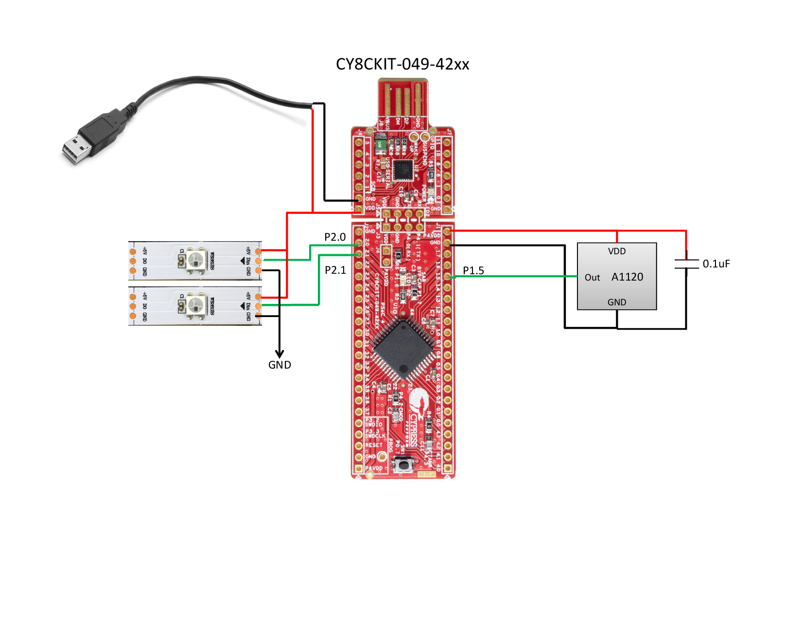
I wanted a speed-reactive effect so I scratched my head a little and settled on a Hall Effect sensor. I chose a three-terminal sensor from Allegro, with the mid-range sensitivity. The A1120 looked good, and had nice leads so I could mount it away from the PSoC board. I used a random round rare-earth magnet from the junk box. Luckily I had a few, because the first one flew off during road tests. Some hot glue and cyanoacrylate and I'm in business.
I got lucky; the distance, strength of the magnet, and sensitivity of the sensor all worked out!
I find endless amusement using the WS2812 LED strips. It's nice to have an addressable scheme so I can make animations and have full color control. They come in strips, individuals, and even nifty rings. I happened to have a bunch of self-adhesive strip laying around. You can get your own from any number of sources like Adafruit, Sparkfun, Ebay, AliExpress, etc.
Finally, I needed some power. This comes from a USB power brick. I had a flat one, 2200mAh capacity, with an on/off button laying around that I could sacrifice for the cause. I'll add a disclaimer here. Since this is strapped UNDERNEATH a skateboard, it's entirely possible that physical damage to the battery pack could result in FIRE. Possibly. I live for danger, though.
I hacked a USB cable up to run the Vbus and Ground lines (red and black, usually) into the VDD and GND vias. I could have slid the Proto module right into the battery pack's charging port, but it's a little easier to remove the pack for charging or the Proto module for reprogramming this way.
Shout out to my friends Velcro and Hot Glue. You're the best. Seriously though, having this stuff easily removable is key. Gotta recharge the pack sometime.
The code was developed in PSoC Creator 3.3. It's a fine tool and I like it.
The handsome and talented Mark Hastings created a PSoC Creator component that takes all of the effort out of driving WS2812 strips. Highly recommended, five stars:
Get your StripLights Component here!
You need to add this to your Creator project dependencies. Unzip the archive, throw it in your PSoC Creator projects directory and point Creator at the one instance of that component or library.
Hint: Project->Dependencies->User Dependencies, add a new dependency.
There is very little in the way of external componentry. The Hall sensor should be locally bypassed so I put a 0.1uF tantalum "drop" capacitor across its power leads. It's hard to see under the hot glue. but I assure you that it's there. The input to the PSoC is simply a pin configured as resistive pullup. It is named "Hall_In" on the Creator schematic, and I somewhat arbitrarily put it on P1.5, which is nearer the bridge end of the PSoC board.
The LED strips are configured as two channels from the StripLights component. Again, the pins are chosen for their physical convenience, so P2.0 and P2.1. I've driven strips in parallel from one I/O but for this I wanted individual control over the strips. And why not? I'm barely using anything on the PSoC.
I went ahead and used the onboard LED as a Hall sensor indicator. In the ISR, the Blue LED pin is simply toggled. It's nice to be able to spin the wheel and see the light flash.If you pull the code from Github, I consider this "Version 1". It's actually not that impressive. The GPIO toggles every time the wheel rotates, and I step the lit LEDs through the "pixel array". After some time without a toggle, it turns the LEDs off.
I have some rudiments of a feet-per-second calculation. My thought is to add a new function that turns on "brake lights" on deceleration, or have a dazzle mode when it captures a new top speed. Could be cool, but right now it's winter time and that's really bad for my skate bearings.
The Creator ProjectA project walkthrough might be nice, right?
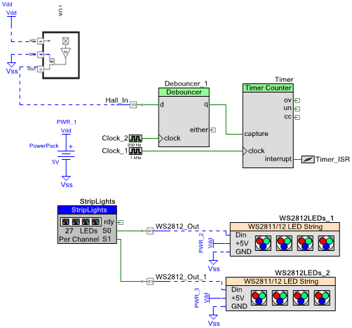
Here's the input capture system. Debouncing is good, although this worked fine without it. Don't tell anyone. The Timer is configured to interrupt on a falling-edge capture (because the Hall sensor pulls the line low). The ISR grabs the current and previous counts, and sets Timer_Capture_Flag. In the main code, I take care of overflow and such then just get a difference in counts between the previous and last captures. Really, though, I'm just calling StepColors(). All of the rest is there for future use for the feet-per-second calculations.
//any Hall captures yet?
        if(Timer_Capture_Flag)
        {
            if(Timer_Capture > Timer_Capture_Last)
                Diff = Timer_Capture - Timer_Capture_Last;
            else
                Diff = (65535 - Timer_Capture_Last) + Timer_Capture;
            Timer_Capture_Flag = 0;
            StepColors();
            NoSpeed = 0;
        }
        //nope, maybe I stopped
        else
        {
            Timeout++;
        }
If you're into this stuff, there's a really detailed treatment here.
StepColors() is fun. I have to reverse the order because I put the battery and PSoC board at the rear of the longboard, and I want the color bands to move from front to back. The LED strips have pixel 0 at the beginning which is at the rear, so this code saves many feet of wire. The offsets are there to put the two colors in slightly different locations. Your aesthetic taste may vary.
void StepColors(void){
    //PixelCounter is used as the main index into the strip's pixel array
    //PixelMask is there because this particular installation is "reversed"
    //so we need to start the motion from the far end of the strip
    if(PixelCounter < 27)
        PixelCounter++;
    else PixelCounter = 0;
    PixelMask = 27-PixelCounter;
    StripLights_MemClear(0x00000000);
    StripLights_Pixel(PixelMask   ,0,PURPLE);
    StripLights_Pixel(PixelMask -1,0,VIOLET);
    StripLights_Pixel(PixelMask -2,0,BLUE);
    StripLights_Pixel(PixelMask -3,1,YELLOW);
    StripLights_Pixel(PixelMask -4,1,ORANGE);
    StripLights_Pixel(PixelMask -5,1,RED);
}
The project also has hooks for an I2C readback, I used it briefly while setting things up. The Bridge Control Panel is a handy thing for graphing variables but it requires a MiniProg3. All of the code for that is commented out.
The bootloadable component is there in case you don't have a MiniProg3 and wish to bootload the Proto module. I find it a little slow when I'm making lots of changes.
Protip: Add a square of electrical tape to the back side of the USB tab on the Proto module. It's just a little bit thin and doesn't always make good contact with your USB port. Also, those USB extension cables are great, you don't have to drag the Proto module all the way back to your laptop or PC to bootload it.
So, that's it for the high points. If you're basically conversant in C, the code is easy. There's not a lot to the schematic and assembly, as you can see by my hamfisted assembly. But, the neighborhood kids like it and I had fun building it. Maybe you will, too?


Comments
Please log in or sign up to comment.