


Hardware components | ||||||
_ztBMuBhMHo.jpg?auto=compress%2Cformat&w=48&h=48&fit=fill&bg=ffffff) |
| × | 1 | |||
 |
| × | 1 | |||
 |
| × | 1 | |||
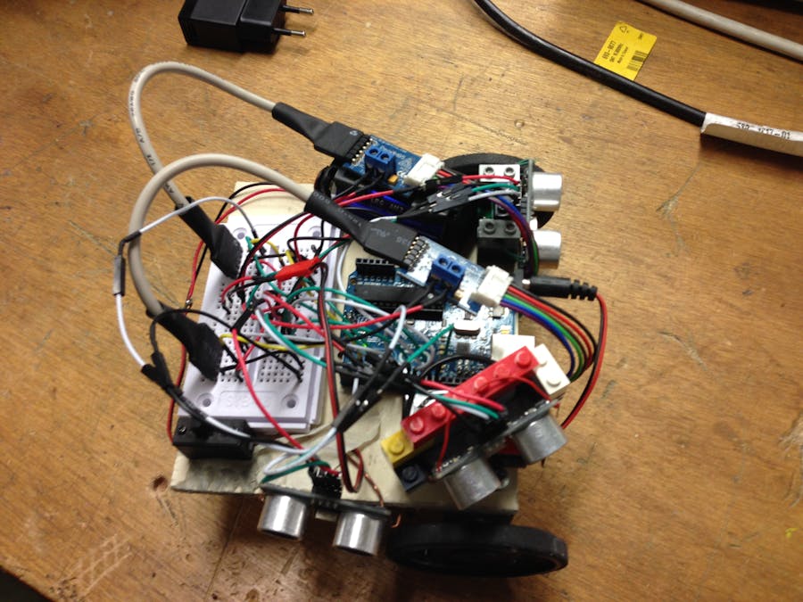
The objective of this project is to resolve a maze. We decided to realize this project for our studies and improve our skills.
The project works like this :
Pin-outOur robot is only connected on digital pin () and a ground pin (called GND).
The two motors have a common power supply (black wire) and Vcc terminal (red wire), not connected to a pin of the Arduino but connected to the H-bridge for the engines to have an external power supply.
The the joint pin to two motors is the pin 8. The pin is connected to the ENABLE pin of the H-bridge (see data sheet) and pin 4 is connected to the two H-bridges borne VCC H.
The GND pin is connected to a ground line connected to the mass of the Arduino because it is necessary that the motor is a common terminal with that of the Arduino.
The SA and SB pins are the pins of the sensor, they are connected to a pin for each sensor output, it is the pin 2.3 of the right engine and 5.6 for the other. This is an arbitrary choice for practical reasons related to its size.
The management terminal is connected to the right motor, the PWM pin 9 and to the left, on the pin 10 in PWM because it needs a PWM signal to control the motor.


Comments
Please log in or sign up to comment.