

Hardware components | ||||||
| × | 1 | ||||
| × | 1 | ||||
 |
| × | 1 | |||
 |
| × | 3 | |||
 |
| × | 1 | |||
 |
| × | 1 | |||
 |
| × | 1 | |||
 |
| × | 1 | |||
| × | 1 | ||||
Software apps and online services | ||||||
 |
| |||||
Hand tools and fabrication machines | ||||||
 |
| |||||
 |
| |||||
 |
| |||||
| ||||||
| ||||||
| ||||||
| ||||||
Are you new to making? Never touched a circuit in your life? Scared of those little wires. Well no worries fellow internet-goer, here is a full detail tutorial on how to build one of the most common props from Star Wars: a Thermal Detonator!
Fortunately, this tutorial also comes packed with a video to help guide you through this process. No fear!
You can use either use this written tutorial AND/OR the video to perform this project. Either will work fine! If one source lacks a detail, ideally the other will work.
I am currently working on my own Mandalorian cosplay, and it's full of bells and whistles that lots of my peers are curious to learn about. So I decided to make a tutorial for them and anyone else getting into this amazing hobby. The thermal detonator can be used on virtually any Star Wars cosplay!
I found a really cool.STL of the thermal detonator online, but it seemed to lack any instruction on how to bring it to life, so I thought that creating this could serve the community well.
The prop works by performing a lighting sequence of LEDs as seen from the Original Trilogy. Each time you press the button, the sequence begins. By pressing and holding, you speed up the lighting sequence until the red LED turns off. At that moment, releasing the switch turns off the sequence.
Internal to the prop, an ON/OFF switch exists, by switching to OFF, you can plug the battery lead into a charger to charge the prop.
**>BUILDING THE PROP<**
To get started, click on the link below to access the Thingiverse item and 3D print the shells and button for the prop.
Thingiverse Thing files for the Thermal Detonator
In addition to this Thingiverse item, also go ahead and print this insert part as well. This will serve as the housing to hold all the electronics into the prop. Check out the files section in this tutorial.
Any material will suffice for these 3D printed parts.
With each 3D printed part, use 2-in-1 Filler/Primer spray paint in alteration with sandpaper to knock out the layers on the surfaces of the parts, being sure to create a clean surface.
Once the surface is nice and smooth, use small amounts of Silver Rub'n'Buff to rub in a metallic shine to the part, giving the prop that unique Star Wars aesthetic.
And that's all for the surface work, pretty easy, but tedious.
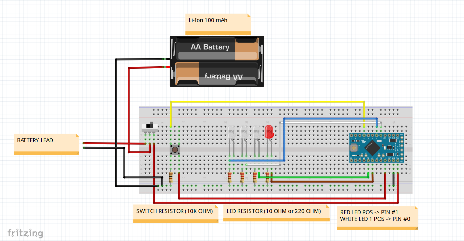
**>BUILDING THE CIRCUIT<**
Now here is where things get interesting. I recommend after each solder connection, using heat shrink to isolate each connection to prevent shorting.
LEVER SWITCH
Start by taking the lever switch (shown below) and bending the lever into a C-shape. This will act as the switch to activate the prop's effect.
Take the lever switch, and position as seen below in the 3D printed insert, and take small dabs of super glue to lock it into place.
Cut out a black ground wire, yellow signal wire, and red power wire to a length of 1.5" [38.1mm] each.
Solder the black ground wire and yellow signal wire to the common terminal of the lever switch.
Solder the red power wire to the terminal on the lever switch that is nominally open (NO).
BATTERY AND ON/OFF SWITCH
Next up, take the battery and cut off the lead of the battery, solder an additional 2.0" [50.8mm] - 2.5" [63.5mm] of wire length to both the battery and battery leads, to create separate entities.
Take the battery, battery lead, and the ON/OFF switch and position them as shown below to begin the solder connections.
Cut a red wire to a length of 3" [76.2mm].
Solder the POS end of the battery to the center terminal of the ON/OFF switch. Solder the POS end of the battery lead to one of the side terminals of the ON/OFF switch. Solder one end of the 3" wire to the other side terminal of the ON/OFF switch.
RESISTORS
Whip out a 10 Ohm (220 Ohm can suffice) and 10K Ohm resistor and cut the lengths of each leg to 0.25" [6.35mm].
Cut out four black ground wires to a length of 1.5" [38.1mm] each and solder each wire to each end of the resistors.
RED LED
Cut a black ground wire and brown signal wire to 3" [76.2mm] each.
Pull out a red LED and cut the legs of the LED to 0.25" [6.35mm] each and the bend the leads to a 90 degree (pi/2 radians) angle.
IMPORTANT: The longer leg of the LED is the positive end, mixing this up could lead you to break the LED.
Solder the brown signal wire to the POS end of the LED and the black ground wire to the NEG end of the LED.
Push the LED into the hole on the top shell of the Thermal Detonator, ensuring that the wires are facing downwards on the prop, as shown below.
WHITE LEDS
Let's start by cutting three black ground wires, two being 1.5" [38.1mm] in length, and the other being 3" [76.2mm] in length.
Take the 3" black wire and lightly cut into the insulation at 0.75" [19.05mm] and 1.25" [31.75mm] from one of the ends of the wire. Slice between those cuts and peel off the insulation to reveal a section of conductor underneath.
Take the two other black wires and solder them to that freshly exposed section of conductor on the 3" wire to create a forked wiring harness, as shown below.
Now, cut three uniquely colored signal wires each at 3" [76.2mm] in length each.
Grab three white LEDs and cut each leg to a length of 0.25" [6.35mm] each. Bend each lead to a 90 degree [pi/2 radians] angle.
Solder each end of the forked grounded wires to the NEG ends of each LED and each signal wire to each POS end of the LEDs to create a spliced wiring array, as shown below.
Take the LED array, and with super glue, glue each LED into their display ports on the lower shell of the Thermal Detonator. Ensure that the wires are facing upwards on the prop.
GROUNDED WIRING HARNESS
Cut two black ground wires at 1.5" [38.1mm] & 2" [50.8mm] each.
Solder one the ends of each wire together to create a simple grounded wiring harness, as shown below.
ASSEMBLY
Whip out the 3D printed insert from before.
Take the two resistors we worked on earlier and place the leads through the holes on the pylon as shown below. Apply a small amount of super glue to the resistors to lock them into place. I prefer to position the 10K Ohm resistor in the upper slot and the 10 Ohm resistor in the lower slot.
Now pull out the Arduino microcontroller, ensure that it is the Adafruit Trinket 5V model, and solder the headers facing away from the top of the board, as shown below.
Locate the large pylon on the 3D printed insert, and take a small dab of super glue to mount the microcontroller to the prop, ensure that the USB is facing upwards and the small reset button on the board is not blocked by the void in the 3D printed part.
Locate the loose end of that 3" red wire coming off the ON/OFF switch and solder that to the pin labeled "BAT".
Take the yellow signal wire from the lever switch and solder that to the pin labeled "#4".
Solder the black ground wire from the lever switch to one end of the 10K Ohm resistor.
Solder the red power wire from the lever switch to the pin labeled "3V".
Take the other end of the 10K Ohm resistor and one of the ends of the 10 Ohm resistor and solder those to the longer end of the grounded wiring harness we made earlier.
Solder the ground wires from the red and white LEDs onto the other side of 10 Ohm resistor.
Solder the ground ends of the Battery and Battery Lead to one of the other ends of the grounded wiring harness.
For the next steps, ensure that the ON/OFF switch is set to off to avoid shorts!!!
Guide the grounded wiring harness through the large channel on the 3D printed insert.
Solder the last open end of the grounded wiring harness to the pin labeled "GND".
Take the brown signal wire from the red LED and solder that to the pin labeled "#1".
Now for these next steps, it's important to know which order you want the white LEDs to light up.
Take the signal wire for the first white LED you want to light up and solder that to the pin labeled "#0".
Take the signal wire for the second white LED you want to light up and solder that to the pin labeled "#2".
Finally, take the signal wire for the third white LED you want to light up and solder that to the pin labeled "#3".
**>FINAL TOUCHES<**
Download the script file and upload the script via Arduino IDE to the microcontroller. If this is your first time using this board, refer to the link below to learn how to use this board for writing scripts.
First using the Adafruit Trinket Mini
Now, go ahead and assemble the insert into the lower shell of the prop. Make sure the insert is flush with the top of the lower shell.
Cut out a small bit of velcro and attach that to the top of the C on the lever switch.
Take the other side of the velcro and attach that to the bottom of the button 3D printed part.
Start assembling the upper shell to the lower shell, making adjustments to the C-shaped lever you can optimally press and release the lever switch from the 3D printed button.
And there ya go! One fully operational Thermal Detonator! (minus the boom boom of course)
I hope this tutorial was useful and informative to you. This was my first ever tutorial on something of this magnitude. It took a ton of work and effort to bring this video to the quality and detail that it is!
Please check out my Twitter where I stay actively engaged.
There I can answer any questions you may have about this. Also a follow would be highly grateful. I would love to know if these tutorials are something that I should continue to work and improve upon.


Comments