I had a digital fish tank thermometer on my tank but I broke the sensor when moving it so I decided to make one myself.
What I wanted was to have the fish tank water temperature displayed on an 16x2 LCD using a DS18B20 sensor.
Then I thought about controlling the two sets of lights I have in the tank. One set comes on (main white light) at 0800 and goes off at 1900 then the night light (blue light) comes on from 1900 to 2100.
With all this I wanted also to have a visual indication of the water temp so I added a RGB led. When the water temp is ideal the led is green (24 - 27 Degrees C), too hot (above 27 Degrees C) and the led goes red, too cold (below 24 Degrees C) and the led goes blue.
And a little bonus I added an LDR so when the house lights go off at night so does the backlight on the LCD.
Here is a picture of the relay unit (dual) one is 12 volts for the blue night light and the other is 240v for the main light.
WARNING: if unsure of doing any wiring don't carry on as 240v is lethal and can kill!
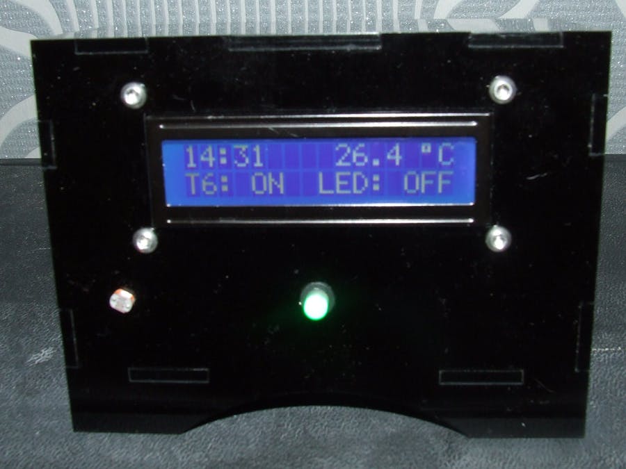
Here is the finshed design
Forgot to mention there is also a clock added for the time keeping of the lights, this will have to be updated by using the set time example for DS1307 RTC.
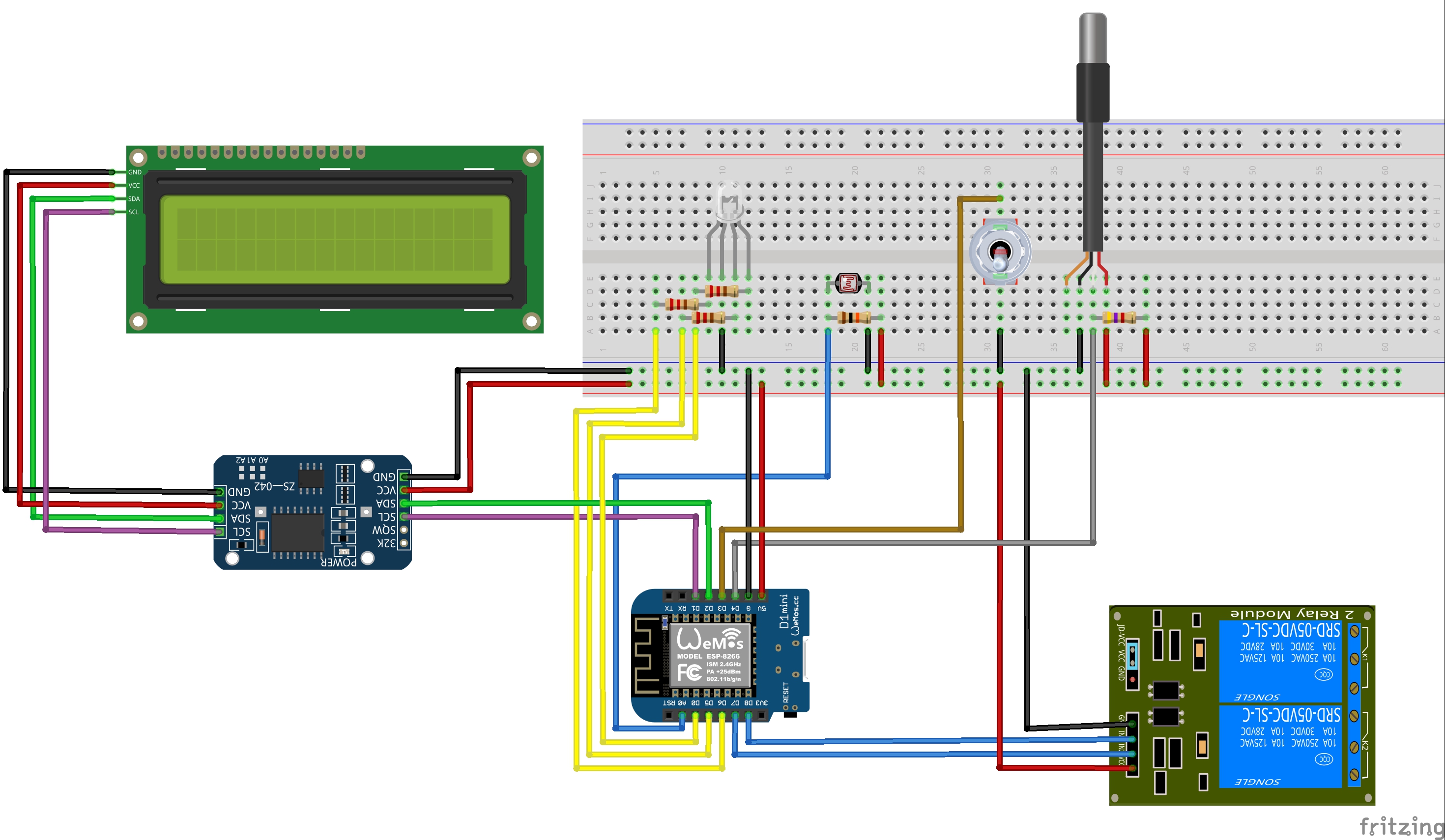
For the build you will need wire for connecting everthing together, the 3 x 220 ohm resistors are connected to the RGB legs of the RGB LED for protection. There is a 10K ohm resistor connected across the LDR and don't forget the 4.7K ohm resistor for the DS18B20 other wise it won't work.
Follow the diagram for connecting it all. The LCD and RTC are I2C connections so I only need 2 wires (and 5v and GND).
In the end I used a 1307 RTC shield for the wemos instead of the DS3231 RTC.
There was intentions of adding a DS18B20 for the air temperature as well which would of been connected to the box but i decided against this as the box is on top of the tank and it would of given false readings.
UPDATE: Just added a switch to turn the main light on when out of hours just in case i need light on in the tank when its dark. I used the spare pin (D3) to wire to the toggle switch and the other end of the switch to GND.
Decared the switch int Switch = D3;
and set it as a pullup input pinMode(Switch, INPUT_PULLUP);
Then altered the IF statements please see code.


_1x_bGT19vVAby.png?auto=compress%2Cformat&w=40&h=40&fit=fillmax&bg=fff&dpr=2)
Comments
Please log in or sign up to comment.