


Hardware components | ||||||
_ztBMuBhMHo.jpg?auto=compress%2Cformat&w=48&h=48&fit=fill&bg=ffffff) |
| × | 1 | |||
 |
| × | 1 | |||
 |
| × | 1 | |||
Software apps and online services | ||||||
 |
| |||||
Hand tools and fabrication machines | ||||||
 |
| |||||
 |
| |||||
PWM – For controlling speed: PWM is a technique where average value of the input voltage is adjusted by sending a series of On/OFF pulses, the average voltage is proportional to the width of the pulses known as Duty Cycle.The higher the duty cycle, the greater the average voltage applied to the dc motor this lead to the highest speed.
H-Bridge – For controlling rotation direction: An H-Bridge circuit contains four switches with the motor at the center forming an H, closing two particular switches at the same time reverses the polarity of the voltage applied to the motor. This leads to a change in the direction of the motor.
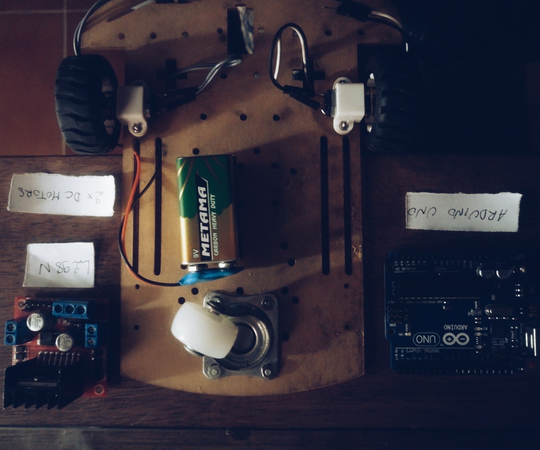
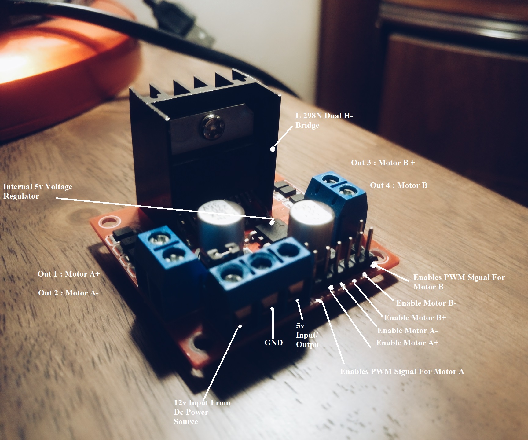
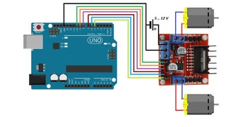
The L298N is a dual-channel H-Bridge motor driver capable of driving a 2x DC motors, making it ideal for building two-wheel robots.
Power Supply :From 'Vs' pin the H-Bridge gets its power for driving the motors which can be 5 to 35V. 'Vss' is used for driving the logic circuitry which can be 5 to 7V. And they both sink to a common ground named ‘GND’.
Warning : if the motor power supply is greater than 12V, you should remove the jumper to avoid the on-board 5V regulator from getting damaged.Also DO NOT supply power to both the motor power supply input and 5V power supply input when jumper is in place.
Output Pins :The L298N motor driver’s output channels for the motor A and B are broken out to the edge of the module with two 3.5mm-pitch screw terminals.
Direction Control Pins : The IN1 and IN2 pins control the direction of the motor A while IN3 and IN4 control the direction of the motor B.
Speed Control Pins :ENA and ENB are used to turn the motors ON, OFF and control its speed. The module usually comes with a jumper on these pins. When this jumper is in place, the motor is enabled and spins at maximum speed. If you want to control the speed of motors, you need to remove the jumpers and connect them to PWM-enabled pins on Arduino.

_3u05Tpwasz.png?auto=compress%2Cformat&w=40&h=40&fit=fillmax&bg=fff&dpr=2)
Comments
Please log in or sign up to comment.