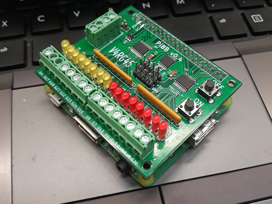
I started working on a 5V buffer board because I needed a friendly, solid interface for my robots. I decided that I needed visual indication of inputs and outputs. Also solid connections that will not get loose from vibration. The first prototype I made was with a perf-board and wires. On the final board, I used KiCad for the design. This is the first time I design a PCB. It took many hours of research and 3 prototypes that I had to scrap. I wanted something easy to solder but in order to fit all the components, I had to use some surface mounted parts. Soldering SMD components seems complicated but really is not. All you need is a small tip iron, De-solder wick, magnifier goggles, small tweezers, and some patience. There are many soldering videos available on YouTube.
The board includes 8 inputs, 12 outputs, 1 analog input, 1 ON button, 1 OFF button. 4 outputs are setup for servo connections. The outputs are rated at 20mA for a total of 70mA for the IC. The board has place for 2 resistors to be used as a voltage divider for the 3.3V analog input. The analog input uses the I2C pins.
The OFF pushbutton is connected to pin 40 and in order to create a shutdown, the file at /boot/config.txt has to be modified to include dtoverlay=gpio-shutdown,gpio_pin=21 and that's it. The LEDs used are high brightness Cree oval and use about 4mA each. The board does not have any overcurrent protection. The board can be fed from the Raspberry Pi 5V. If servos are connected to the center terminals, then 5V has to be supplied at the side terminals. Only one power source is needed, ether the terminals or the micro USB at the Pi. I ordered the PCB from China and it cost about $20 dollars for 10 pieces. I ordered it with 2oz copper for thicker layers.
During the assembly, first solder the surface mounted components. Test all the pins to see if if you created any shorts. Then solder the 40 pin connector. At this point connect to the Raspberry Pi and test all the GPIOs to make sure everything is going OK. You will need to write some code for this and a voltmeter to measure the outputs. Now solder the rest of the components.
This is a good project to learn soldering surface mounted components and also learning to control GPIOs without having to wire any LEDs. If you are ready to make your own board, go for it.


_4YUDWziWQ8.png?auto=compress%2Cformat&w=48&h=48&fit=fill&bg=ffffff)

_Ujn5WoVOOu.png?auto=compress%2Cformat&w=40&h=40&fit=fillmax&bg=fff&dpr=2)


Comments
Please log in or sign up to comment.