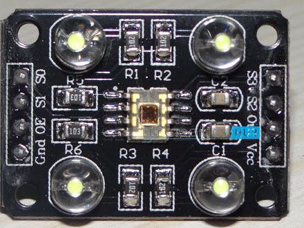
SensorWorking-
Sensor Connection-LHS pins are of nodemcu and RHS pins ore of color sensor
Nodemcu pins---->color sensor pins
- D4--->S0
- D5--->S1
- D6--->S2
- D7--->S3
- GND--->OE
- D8--->OUT
- 3.3V--->VCC
- GND--->GND
Arduino code for sensor-
check the output on serial monitor.
const int s0 = D4;
  const int s1 = D5;
  const int s2 = D6;
  const int s3 = D7;
  const int out = D8;
  int red = 0;
 int green = 0;
 int blue = 0;
 void setup()
  {
    Serial.begin(9600);
  pinMode(s0, OUTPUT);
    pinMode(s1, OUTPUT);
    pinMode(s2, OUTPUT);
    pinMode(s3, OUTPUT);
    pinMode(out, INPUT);
     digitalWrite(s0, HIGH);
    digitalWrite(s1, HIGH);
  }
void loop()
 {
 color();
  Serial.print("R Intensity:");
    Serial.print(red, DEC);
   Serial.print(" G Intensity: ");
   Serial.print(green, DEC);
   Serial.print(" B Intensity : ");
    Serial.print(blue, DEC);
    if (red < blue && red < green && red < 20)
  {     Serial.println(" - (Red Color)");     }
   else if (blue < red && blue < green)
   {     Serial.println(" - (Blue Color)");     }
   else if (green < red && green < blue)
   {     Serial.println(" - (Green Color)");     }
 else{  Serial.println();    }
 delay(300);
}
  void color()
 {      digitalWrite(s2, LOW);
    digitalWrite(s3, LOW);
//count OUT, pRed, RED
    red = pulseIn(out, digitalRead(out) == HIGH ? LOW : HIGH);
  digitalWrite(s3, HIGH);
  //count OUT, pBLUE, BLUE
 blue = pulseIn(out, digitalRead(out) == HIGH ? LOW : HIGH);
    digitalWrite(s2, HIGH);    //count OUT, pGreen, GREEN
 green = pulseIn(out, digitalRead(out) == HIGH ? LOW : HIGH);
 }
thingsio.aiprocess-
check out these youtube tutorials on how to use thingsio.ai and do projects-
https://www.youtube.com/channel/UCsFRKAPmNWyT-5-n1-QtjLg
1) google thingsio.ai
2) register yourself (or) make an account
3) click on new project button on top menu
4) go to sample code option's --> nodemcu -->LM35 --> copy
5) paste it on arduino ide
6) merge the arduino code above in copied code systematically(merge where it should be).
7)after merging just upload and check the dashboard on thingsio.ai.
See the code below


Comments
Please log in or sign up to comment.