Raspberry Pi Pico is a little, fast, and versatile board built using RP2040, a brand new microcontroller chip devised by Raspberry Pi in the UK. You can have a look at the datasheet of Pico. You will find the getting started guide on Pi Pico here.
Below are the features of the RP2040 microcontroller:
- Dual ARM Cortex-M0+ @ 133MHz
- 264kB on-chip SRAM in six independent banks
- Support for up to 16MB of off-chip Flash memory via dedicated QSPI bus
- DMA controller
- Fully-connected AHB crossbar
- Interpolator and integer divider peripherals
- On-chip programmable LDO to generate core voltage
- 2 on-chip PLLs to generate USB and core clocks
- 30 GPIO pins, 4 of which can be used as analogue inputs
- Peripherals ◦ 2 UARTs ◦ 2 SPI controllers ◦ 2 I2C controllers ◦ 16 PWM channels ◦ USB 1.1 controller and PHY, with host and device support ◦ 8 PIO state machines
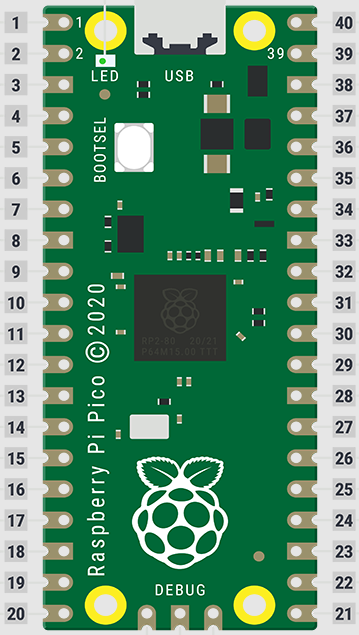
You will find the pinout details of the MCU below
You will see that you will be able to blink a LED on Pico in the similar way how one blinks an LED in Arduino. We will have both setup() and loop() functions in the same way how it is there in the case of Arduino. LED_BUILTIN is connected to pin 25 of the RP2040 chip.
Raspberry Pi Pico SimulatorThe preview of the Raspberry Pi Pico simulator is shown here
The code is given in the code section below
// LED_BUILTIN in connected to pin 25 of the RP2040 chip.
// It controls the on board LED, at the top-left corner.

void setup() {
  pinMode(LED_BUILTIN, OUTPUT);
}

void loop() {
  digitalWrite(LED_BUILTIN, HIGH);
  delay(500);
  digitalWrite(LED_BUILTIN, LOW);
  delay(500);
}


Comments
Please log in or sign up to comment.