


The inspiration for this project arose when I discovered an old robotic arm in our Robotics Club, AeRobotix INSAT. Unfortunately, its condition was suboptimal due to years of neglect and disuse. You can view the original robotic arm at http://youpi.forler.ch/, named the YOUPI Robot.
The primary goal of the project is to construct an automated robotic arm designed for sorting colored objects. This arm will efficiently place items into predefined areas based on their respective colors. The robotic arm will be managed by the real-time operating system FreeRTOS.
In real-world industrial applications, robotic arms serve a variety of functions, including welding, materil handling, thermal spraying, painting, and drilling.
Mechanic DIYsAt the outset of the project, certain components were severely damaged. Consequently, I replaced elements such as the damaged gearing and blocked stepper motors. Additionally, I introduced lubrication liquid to enhance various transmissions and mechanical connections. Unfortunately, the effector's condition was also in a deteriorated state, necessitating its replacement.
To power up this robotic arm, I used an ATX power supply because it is sufficient for this application as it can generate 24V DC for the stepper motors and 12V DC for the vacuum pump. Furthermore, It is small and well-suited to be fixed under the arm.
Meanwhile, during my research for a suitable stepper driver, I found that the A4988 stepper driver was a good choice due to its compact size and affordable price. Additionally, I utilized a CNC shield V3 to alleviate circuit congestion
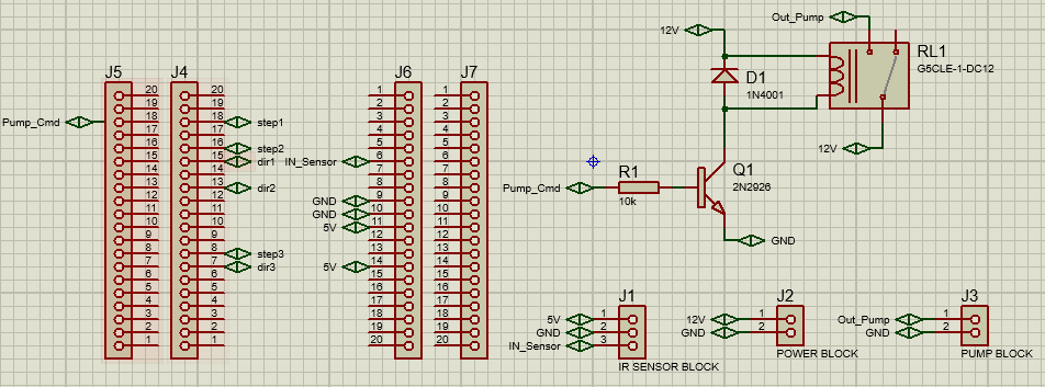
In the interest of reducing wiring and making the project more organised, I designed a simple circuit using ISIS Proteus. It contains a relay driving circuit which will supply the vacuum pump with the necessary current and an IR object sensor which will check the presence of the colored objects. Moreover, The stepper motors connections are established directly with CNC shield V3.
Circuit diagram:
After printing the design, soldering the components and testing the full functionalities :
Unfortunately, the original robot effector suffered significant damage. Consequently, I opted to design my own effector using SolidWorks. The new design uses pneumatic energy, utilizing a vacuum pump and an appropriate ventose.
In this part of the project, I used the computer vision library Open-CV to detect the colored objects and determine their coordinates. This program will run on my computer and will get the data frames from the webcam ( The camera is fixed on the top of the arm ). Then, it will analyse those frames and check for objects within the defined radius. The order of priority is (First to Last):
When an object is detected, it simply sends its coordinates and color to the STM32 Micro-controller. Then, the main program of the arm will convert these coordinates to the robot's real coordinate system.
You can find this program Object_Sorting.py in the Code section below or in my GitHub repository: https://github.com/AlaHammouda/Robotic-Arm-Project.
I used the range-detector script in the imutils library to fix the lower and upper boundaries in the HSV color space.
Test Demonstration:
Main program :At the apex of the pyramid, I programmed the arm utilizing the STM32F410RB NUCLEO Board. Recognizing the need to control the stepper motors simultaneously, I discovered that a real-time operating system (RTOS) not only enhances efficiency but also enables the breakdown of a complex problem into simpler components. This approach allows one to concentrate on the development of each task rather than managing scheduling intricacies. FreeRTOS, a free real-time embedded operating system, emerged as the optimal solution. It is professionally developed, rigorously quality-controlled, robust, and well-supported. Moreover, it is compatible with various popular microcontrollers, including the STM32.
- Theoretical study :
To determine the specific joint angles (θ1, θ2, θ3, θ4) for any (x, y, z) coordinates of the effector, as it is basically an essential operation in the program, I drew a simplified scheme:
The resolution of this system of equations is so complex and will lead us to an infinite number of solutions. Therefore, I decided to simplify them by fixing the angle θ4= -π/2 rad :
Now, the resolution of the system will give us two solutions. I chose the one in which (θ2>θ3) because it is more adapted and convenient for the arm :
This solution is only determined and tested with :
- Code Implementation :
After configuring the microcontroller settings in STM32CubeMX and generating the setup code in Keil uVision IDE, the only task left is to implement the code.
The program's general idea is very simple, It's just about running four tasks in FreeRTOS: Three of them are managing the stepper motors and the fourth one is handling specific operations in every state of the arm.
In order to ensure real time interaction with the objects, the communication with my computer is established using UART interrupts.
Including libraries and declaring variables : main.c(56)
Definition and creation of tasks : main.c(208)
Start the RTOS scheduler: main.c(233)
Implementing Set_Joint_Angles( ) : This function will convert (x, y, z) command coordinates to (θ1, θ2, θ3, θ4) joint angles as we have already explained in the previous section : main.c(485)
Implementing Stepper1_Task_function( ) : this function will handle the rotation of Joint1. The same code is in the Stepper2_Task_function( ) and Stepper3_Task_function( ) main.c(516)
Implementing Main_Arm_Task_function( ): This function will handle the state of the arm and the appropriate action in each situation: main.c(600)
Declaring variables in stm32f4xx_it.c(41) :
Receiving and handling data of UART interrupts : stm32f4xx_it.c(104)
You can find those files ( main.c, stm32f4xx_it.c ) in the code section below. The full program project (Keil µVision + STM32cubeMX files ) is available in my GitHub repository : https://github.com/AlaHammouda/Robotic-Arm-Project.
Testing the Main Program:
FinallyThis project has been a remarkable experience preceding the completion of my engineering studies. I applied a significant amount of knowledge acquired during my academic studies and extracurricular activities. Additionally, I acquired new skills, particularly in computer vision and embedded systems programming.
Finally, I would like to express my gratitude and appreciation to my wonderful family at AeRobotix INSAT for the invaluable support and the wealth of knowledge I gained throughout the course of this project.
If you need more information, don't hesitate to contact me : hammouda.alaaeddine@gmail.com


Comments
Please log in or sign up to comment.