


Hardware components | ||||||
 |
| × | 1 | |||
| × | 1 | ||||
| × | 1 | ||||
Software apps and online services | ||||||
 |
| |||||
| ||||||
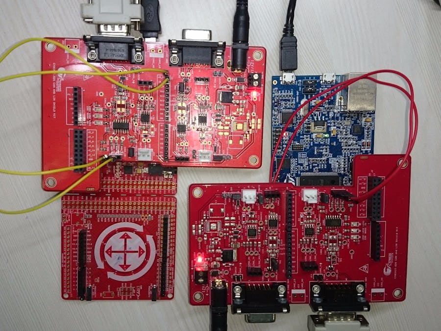
This code example demonstrates the configuration of FM4 S6E2GM Pioneer Kit and CY8CKIT-046 for CAN communication using CY8CKIT-026 as the CAN transceiver. The FM4 S6E2GM sends data for ON/OFF status, color, and brightness of an RGB LED over CAN to PSoC 4L on CY8CKIT-046. The RGB LED on CY8CKIT-044 changes its color and brightness based on data received. PSoC 4M retransmits RGB LED data (ON/OFF stats and color) back to FM4 S6E2GM and RGB LED on FM4 S6E2GM Pioneer Kit operates as per data received.
Requirements- Tool: PSoC Creator™ 4.0 (PSoC 4 M-Series) or later, IAR Embedded Workbench IDE 7.50.2.10505(FM4 S6E2Gx series), PDL 2.1.0
- Programming Language: C ( ARM GCC 4.9.3 and MDK compilers), C for IAR
- Associated Parts: PSoC 4200-L, FM4
- Related Hardware: CY8CKIT-046 PSoC® 4 L-Series Pioneer Kit, FM4-176L-S6E2GM, two CY8CKIT-026 kits
Hardware Connections for FM4 Kit
To use CY8CKIT-026 with an FM4 Kit (FM4 S6E2GM Pioneer Kit), make the following connections:
1. To connect CY8CKIT-026 with the FM4 kit, connect extra headers to CY8CKIT-026.
2. Connect CY8CKIT-026 on top of the FM4 kit.
3. Make connections as follows:
- CN15_8 of FM4-KIT to J19_2(CAN1_Rx) of CY8CKIT-026
- CN15_9 of FM4-KIT to J19_1(CAN1_Tx) CY8CKIT-026.
4. Connect a micro USB cable to the FM4 kit.
5. Place the jumper J13 on CY8CKIT-026.
6. Power the Shield kit with a 12-V/1-A input and connect the DB9 connector to CY8CKIT-026.
Hardware Connections for PSoC 4L Kit
To use CY8CKIT-026 with CY8CKIT-046, make the following connections:
1. Make sure that the jumper J9 on the baseboard (CY8CKIT-046) is in the 3.3V position.
2. Connect CY8CKIT-026 on top of CY8CKIT-046.
3. Place the jumper on pin 2 and 3 of the J20 connector.
4. Connect J3_10 to J19_2 (CAN1_RX) and J3_9 to J19_1 (CAN1_TX) using connecting wires.
5. Connect a USB cable to CY8CKIT-046 for observing the LED data on Terminal.
6. Connect other end of DB9 connector to CY8CKIT-026.
Testing
Program the CAN_Rx_PSoC4L project to CY8CKIT-046. Open CAN_FM4 project in IAR. You find the project in following path:
CAN_FM4-->s6e2gmxj -->projects-->iar
Download and debug the project by clicking on '1' in following figure. Once debug is started click on run, '2', in the following figure.
Once the code starts running you will see the RGB LED glowing on CY8CKIT-046 in the following pattern:
At the same time RGB LED on FM4 kit will glow with same color as on CY8CKIT-046.


Comments
Please log in or sign up to comment.