


Hardware components | ||||||
 |
| × | 1 | |||
| × | 1 | ||||
| × | 1 | ||||
Software apps and online services | ||||||
 |
| |||||
| ||||||
This code example demonstrates the configuration of FM4 S6E2GM Pioneer Kit and CY8CKIT-044 for LIN communication using CY8CKIT-026 as the LIN transceiver. The FM4 S6E2GM sends data for RGB LED status over LIN to PSoC 4M on CY8CKIT-044. The RGB LED on CY8CKIT-044 changes its color based on commands received.
Requirements- Tool: PSoC Creator™ 4.0 (PSoC 4 M-Series) or later, Keil uVision5 (FM4 S6E2Gx series), PDL 2.1.0
- Programming Language: C ( ARM GCC 4.9.3 and MDK compilers), C for Keil
- Associated Parts: PSoC 4200-M, FM4
- Related Hardware: CY8CKIT-044 PSoC® 4M -Series Pioneer Kit, FM4-176L-S6E2GM, two CY8CKIT-026 kits
CY8CKIT-044 & CY8CKIT-026:
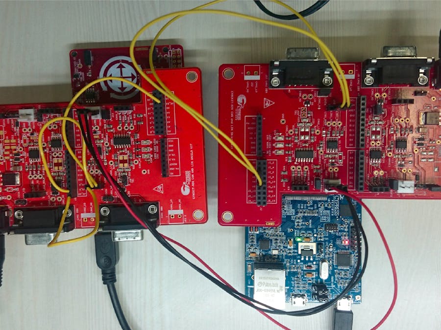
1. Plug the CY8CKIT-026 kit on to the CY8CKIT-044 through Arduino connector as shown in Figure 1.
2. Using the jumper wires, make the following connections between Arduino header and LIN1 transceiver:
a. J3_10 (SCL) to J15_1 (LIN1_RX)
b. J3_9 (SDA) to J15_2 (LIN1_TX)
c. J2_13 to J15_3 (LIN1_NSLP)
3. Remove the jumper on J20_1 and J20_2 pins and place it between J20_3 and J20_4 pins.
4. Make sure that a jumper is placed on J16 header.
5. Connect the CY8CKIT-044 PSoC 4 M-Series Pioneer Kit to PC using a USB to Mini cable.
FM4-176L-S6E2GM – MCU Pioneer Kit & CY8CKIT-026:
1. Plug the CY8CKIT-026 kit on to the FM4-176L-S6E2GM – MCU Pioneer Kit through Arduino connectors as shown in Figure 2.
2. Using the jumper wires, make the following connections between Arduino header and CAN1 transceiver:
a. A2 (J2_5) to J15_1
b. A4 (J2_9) to J15_2
3. Remove the jumper on J20_1 and J20_2 pins and place it between J20_3 and J20_4 pins.
4. Place a jumper on J16 header.
5. Connect 12V/1A power supply to J11 power jack on CY8CKIT-026.
6. Connect the FM4-176L-S6E2GM – MCU Pioneer Kit to PC using a USB to Micro cable.
Testing1. Connect both the CY8CKIT-026’s using a 3-pin female-to-female on J14 connector on both the boards.
2. Switch ON the 12V/1A power supply.
3. Press and release the switch ‘SW2’ on the FM4-S6E2GM Pioneer Kit.
4. Upon pressing the SW2 switch, the LIN master (FM4-S6E2GM Pioneer Kit) transmits a LIN frame and the LIN slave receives the frame and changes the RGB LED color. And it sends the RGB LED status back to LIN master.
5. To observe the data that is transmitted through LIN bus using UART, connect the FM4-S6E2GM baseboard to a PC using a USB cable, and then perform these steps:
a. Open any serial terminal software (Tera Term software is shown here as an example).
b. After selecting appropriate COM port (For example COM37 in Figure 20), set the Baud rate to 115200, Parity = none, Stop bit = 1, as shown in Figure 3.
c. Upon transmitting/receiving the data to/from the LIN slave, FM4 writes the data bytes to UART. You can observe the data on the UART serial terminal software, as shown in Figure 4.
6. Observe the CY8CKIT-044’s on board RGB LED color which is varying continuously upon receiving the LIN messages from the FM4-176L-S6E2GM – MCU Pioneer Kit.


Comments
Please log in or sign up to comment.