Hi, this is the second pin badge I've made, I started the project when I saw the defcon badges.
I wanted something to use daily, it had to be fancy, comfortable, cheap and I had to be proud of wearing it, so I began looking for a character I like. Boom!!!
I like "Pikachu." Who doesn't?Idea
I did a geek style drawing this "pixel art."
The copper is exposed so you'll see the ENIG process getting that gold finish, the soldermask was black to mark the profile and details, this is a game of how you use PCB layers.
Once the character was defined I replicate the hardware used in prototype.
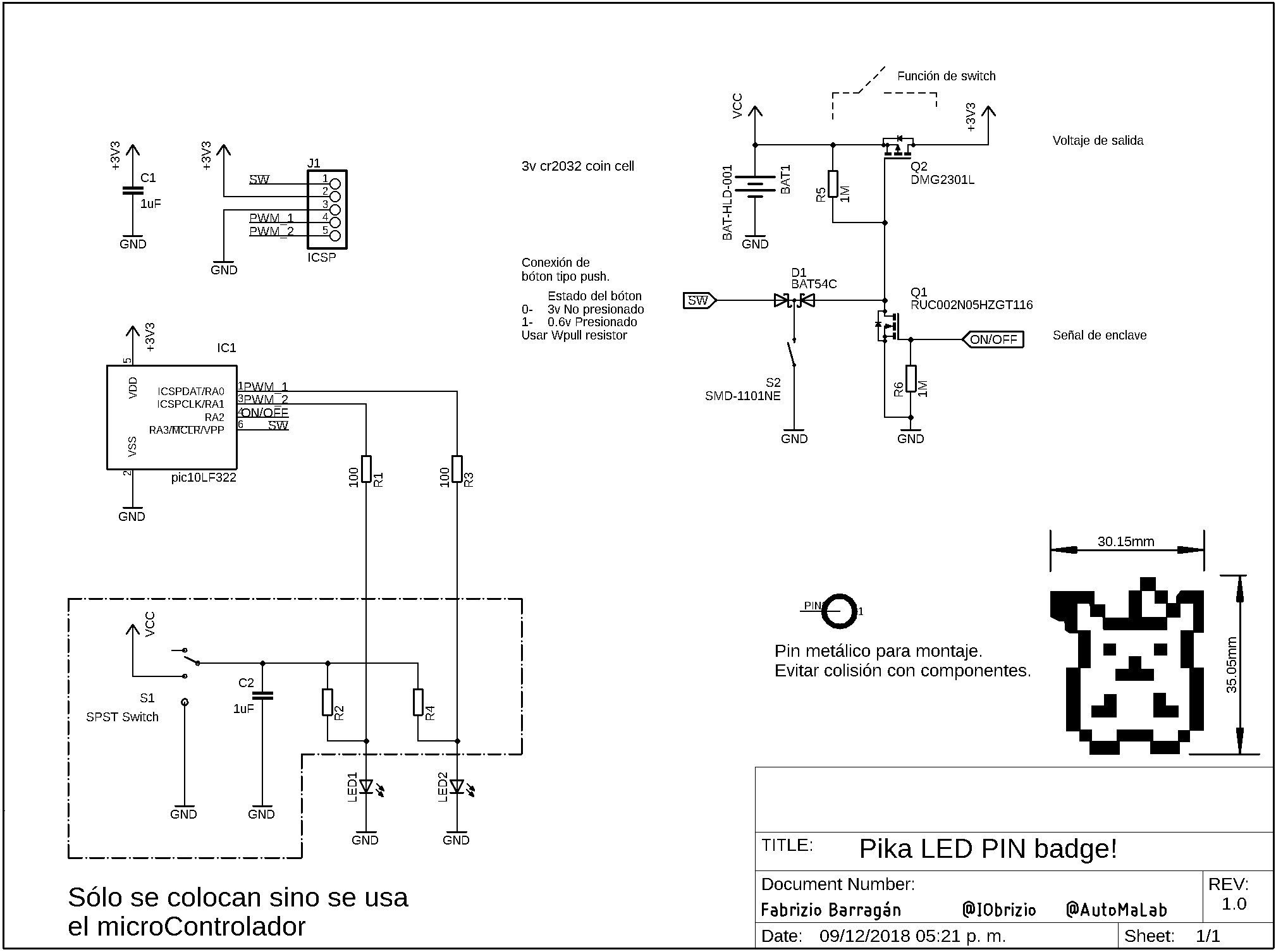
A requirement was to use minimum hardware so it uses one of the smallest mcu, a 6 pin count PIC10LF322, capable to run from 3.6v until 1.8v, enough to light up LEDs and maximize the battery use.
Two pins for two LEDS, one pin for the push button and the last one for the ON/OFF pin control. This pic is tiny but powerful. :D
The circuit is disconnected from the battery.
When you press the button the P mosfet will be activated letting the energy flow, then imediatly the PIC10LF322 will be powered and it set the "ON/FF" pin to ON activating the N mosfet, it will stay "ON" until the "mcu" turns itself OFF.
It's an electronic switch.
The way the "mcu" detects a pressed button is doing a polling to the "SW pin" with a timer event, internally it has a weak PULL UP, if the botton is pressed the voltage at pin "SW" will drop to 0.3v, the Voltage forward D1, the "mcu" reads a "0" wich means " botton pressed" and it will change the mode.
It has 10 modes, the last is for turn OFF.
In OFF mode the P mosfet stops conducting and diconects the circuit from the battery.
The PCB was a challenge, most of time the PCB shape is just rectangular and you can do it directly on PCB CAD program but this time was an exception, so I draw the pikachu shape and export it as DXF file then imported into Eagle(The tradicional way).
It can be fast and easy with autodesk fusion 360, pulling the complex PCB profile directly to your board.
Now I knew it and I'm working with this tool.
Look at this!
I avoid mounting components on the top face because I desire to keep an aesthetic look, just the LEDs.
On the back side you find the cr2032 battery holder wich take almost all the workspace.
The components are tight but you could easily do a hand soldering. The firts pin badge was assembled with a soldering iron tip. So can do it too ;D!
At the center you'll see a big pad, it's for the tie tack pin, there's no hole, just a place to solder, it has a good mechanical contact and holds well.
Dimension : The pcb pin is 0.8mm width, 30mm large and 35mm height.
- Manually put the solder paste and components.
- Turn the heat up to 180-210ºC
- Move the heat over all the PCB to not stress it.
- The battery holder, button and tack pin were mounted with soldering iron tip.
Check the video
How It LooksThe first place where I show the pin badge was at Makers GDL, a maker comunity in Guadalajara, Mexico.
It's a great place, lot of tools, nice people ready to help you and also pet frendly.
They host an event every month called "Makers Night" were you can share your project of any kind and talk about it, that week was about "badges".If you want to know what are they planning just go to this link.
How to Get One?If you want to buy one or 1 million just send me a DM, XD just kidding.
I have a some of them, send me a message or check at tindie Store.
either way the gerber files are uploaded so you can fabricate them wherever you want.
I'm on twitter, you can see what's going on @IObrizio
I hope you enjoy this gadget
Thank you, best regards!


Comments
Please log in or sign up to comment.