Fabrizio
Published © GPL3+

Xmas Tree Pin Badge & Ornament

Now I'm doing a seasonal LED pin badge. This time it's for Christmas. Blink, blink, happy holidays!

IntermediateFull instructions provided2 hours1,313

Things used in this project

Hardware components

BAT-HLD-001
×1
1 uF capacitor smd 1206
×1
Microchip pic10LF322
×1
5 mm LED: Red
5 mm LED: Red
×6
Tie tack pin
×1
Resistor 100 ohm
Resistor 100 ohm
×3
Push button
×1
Custom PCB
Custom PCB
×1
Coin Cell Battery CR2032
×1

Software apps and online services

Autodesk EAGLE
Autodesk EAGLE
Fusion
Autodesk Fusion
gerbv
Microchip XC8 compiler

Hand tools and fabrication machines

Soldering iron (generic)

Story

Read more

Schematics

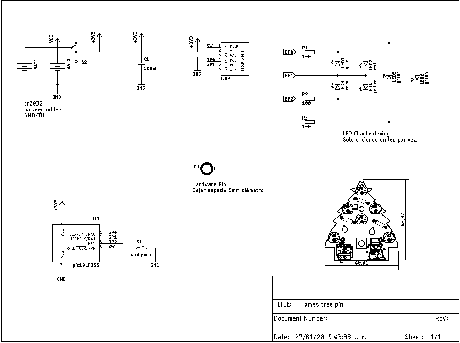
Xmas tree pin badge Schematic

This contain all files.

Eagle Board ,gerbers & Code Files including the HEx files to just flash it!

Code

Xmas tree LED pin badge code

C/C++
This is the main program, you can modify the flashings patterns.
Animation table array,1 for LED ON or 0 to turn LED OFF.
/* 
 * File:   main.c
 * 
 * Author:  Fabrizio Barragan 
 * Twitter: @IObrizio
 * 
 * XMAS TREE PIN LED BADGE & ORNAMENT
 * 3v battery powered (cr2032)
 * Low power device
 * One button turn tu switch flashing patterns
 * One switch to Power On/Off
 * 6 LEDs controlled by charlieplexing technic at 83Hz frequency.
 * 
 * PCB made on Autodesk Eagle free version
 * Code on MPLABX & XC8
 * This is a little mcu " pic10LF322 " love it!
 * 
 * Any question send DM
 */


#include <xc.h>
#include "config_bits.h"

#include <stdint.h>

#define _XTAL_FREQ  4000000 // 4MHz INTRC Frequency
//
#define boton_RA3   PORTAbits.RA3       // Leer boton de entrada

#define menu_items 8        // solo hay 8 niveles en el menu
static const char animation_table[][6] = {

    {1, 0, 0, 0, 0, 0}, //0
    {0, 0, 1, 0, 0, 0},
    {0, 0, 0, 1, 0, 0},
    {0, 0, 0, 0, 1, 0},
    {0, 0, 0, 0, 0, 1},
    {0, 1, 0, 0, 0, 0}, //5

    {1, 0, 0, 0, 0, 1}, //6
    {1, 1, 0, 0, 0, 1},
    {1, 1, 1, 0, 1, 1},
    {1, 1, 1, 1, 1, 1}, //9


    {1, 0, 1, 0, 0, 0}, //10
    {0, 1, 0, 1, 0, 0},
    {0, 0, 0, 0, 1, 1}, //12


    {1, 1, 0, 0, 0, 0}, //13
    {0, 0, 0, 0, 1, 1},
    {0, 0, 0, 1, 1, 0},
    {1, 0, 1, 0, 0, 0}, //16

    {0, 1, 1, 0, 0, 1}, //17
    {1, 1, 0, 0, 1, 0},
    {0, 1, 0, 1, 0, 0}, //19

    {0, 0, 0, 0, 0, 0}, //20
    {0, 0, 0, 1, 0, 0},
    {0, 0, 1, 1, 0, 0},
    {0, 0, 1, 1, 1, 0},
    {0, 1, 1, 1, 1, 0},
    {1, 1, 1, 1, 1, 0},
    {1, 1, 1, 1, 1, 1}, //26

}; //Se almacena como byte para portar facilmente,tambien se puede almacenar por bit

uint8_t animation_time; // repeticones * 18ms ( Una animacion dura 18ms)
uint8_t animation_index_L = 0; // indice inferior
uint8_t animation_index_H = 26; // indice superior para poder recorrer animaciones de array Desde-- hasta

uint8_t button_state = 0; //   detecto boton presionado

volatile uint8_t menu = 0; //en que animacion inicia?
volatile uint8_t menu_now = 1; // Diferente a menu para poder iniciar donde apunta menu

char ledstate[6] = {0};

void my_delay_ms(uint8_t time_ms); // retardo en ms,  hasta 255ms NO SE USO
void show_led(uint8_t table_index); // Enciende el LEd correspondiente durante 1ms
void show_animation(uint8_t rep_time, uint8_t animation_indx_L, uint8_t animation_indx_H);

void main(void) {

    //Configuración de Oscilador Interno 4MHz

    // LFIOFR 31.25KHz_osc_not_ready; HFIOFS unstable; HFIOFR 16MHz_osc_not_ready; IRCF 4MHz; 
    OSCCON = 0x50; // 4MHz (IRCF = 0101 0000)
    // CLKROE disabled; 
    CLKRCON = 0x00;
    // SBOREN disabled; BORFS disabled; BORRDY BOR Circuit is inactive; 
    //    BORCON = 0x00;
    //    // WDTPS 1:65536; SWDTEN OFF; 
    //    WDTCON = 0x16;

    //Configuración de puertos

    ANSELA = 0; // NO ANALOG
    OPTION_REGbits.nWPUEN = 0;
    WPUA = 0b1000; // Pull UP Resistor RA3
    LATA = 0;
    PORTA = 0;
    TRISA = 0;

    // RA3 <- MCLR Button A  // Timer0 hace polling boton de entrada
    // RA2 -> LED   0
    // RA1 -> LED   1
    // RA0 -> LED   2 

    // Timer0
    OPTION_REGbits.T0CS = 0; // 0 = Internal instruction cycle clock (FOSC/4)
    OPTION_REGbits.PSA = 0; // 0= Prescaler is assigned to the Timer0 module
    OPTION_REGbits.PS = 0b110; // 1:128

    TMR0 = 180; // 10ms overflow
    INTCONbits.TMR0IF = 0; // clear flag
    INTCONbits.TMR0IE = 1; // Enable Timer0 Int

    // Enable the Global Interrupts
    INTCONbits.PEIE = 1;
    INTCONbits.GIE = 1;

    while (1) {
        // Add your application code
        if (menu > menu_items)menu = 0; // Se llego al ultimo item del menu?

        if (menu != menu_now) { // sí hubo un cambio 
            menu_now = menu;

            switch (menu) {

                case 0:
                    animation_time = 100;
                    animation_index_L = 0;
                    animation_index_H = 26;
                    break;

                case 1:

                    animation_time = 25; // animation time * 18ms
                    animation_index_L = 10;
                    animation_index_H = 12;
                    break;

                case 2:
                    animation_time = 50; // animation time * 18ms
                    animation_index_L = 0;
                    animation_index_H = 9;
                    break;

                case 3:

                    animation_time = 30; // animation time * 18ms
                    animation_index_L = 13;
                    animation_index_H = 16;
                    break;

                case 4:

                    animation_time = 150; // animation time * 18ms
                    animation_index_L = 20;
                    animation_index_H = 26; //prende de 1 por 1 hasta full
                    break;

                case 5:

                    animation_time = 40; // animation time * 18ms
                    animation_index_L = 17;
                    animation_index_H = 19; //
                    break;

                case 6:
                    animation_time = 15;
                    animation_index_L = 0;
                    animation_index_H = 26;
                    break;

                case 7:

                    animation_time = 200; // animation time * 18ms
                    animation_index_L = 6;
                    animation_index_H = 9;
                    break;

                case 8:
                    animation_time = 30;
                    animation_index_L = 0;
                    animation_index_H = 5;
                    break;

            }//switch menu
        }//if menu != menu now

        show_animation(animation_time, animation_index_L, animation_index_H);
        //Muestra los fotogramas indicados por index L y H , 
        //asi mismo el tiempo que cada fotograma se repite

    }//loop
}// main loop

/***       INTERRUPT SERVICE ROUTINE           ***/
void interrupt isr(void) {
    //----------------- TIMER0 --------------------------------
    if (INTCONbits.TMR0IE == 1 && INTCONbits.TMR0IF == 1) {

        button_state <<= 1; //rotate                

        if (boton_RA3 == 0) {
            button_state |= 1; //bit set
        }//if
        else {
            button_state &= ~(1 << 0); //bit clear
        }//else

        if (button_state == 0x1F) { //filtro llena con polling
            ++menu;
        }//if button
        // Pequeño filtra que revisa que minimo se haya presionado 5veces x TMR0 overflow,osea 10ms

        TMR0 = 180; // 180Precarga Tmr0/desborde en 10ms aprox

        INTCONbits.TMR0IF = 0; // Limpiar bandera Tmr0

    }// TRM0 interrupt
    //------------------------------------------------------------
}// ISR

void my_delay_ms(uint8_t time_ms) {

    for (uint8_t x = 0; x < time_ms; x++) {
        __delay_ms(1);
    }
}

void show_led(uint8_t table_index) {
    for (uint8_t x = 0; x < 6; x++) { //recorre cada bit de animacion)solo hay 6 leds

        ledstate[x] = animation_table[table_index][x]; // lee byte de tabla

        if (ledstate[x] > 0) { //enciende LED  

            switch (x) {

                case 0:
                    TRISA = 0b1100;
                    LATA = 0b0010;
                    break;

                case 1:
                    TRISA = 0b1100;
                    LATA = 0b0001;
                    break;

                case 2:
                    TRISA = 0b0001;
                    LATA = 0b0100;
                    break;

                case 3:
                    TRISA = 0b0001;
                    LATA = 0b0010;
                    break;

                case 4:
                    TRISA = 0b0010;
                    LATA = 0b0100;
                    break;

                case 5:
                    TRISA = 0b0010;
                    LATA = 0b0001;
                    break;

            }//switch encender LED
        }// revisa si debe encenderse un led o quedar apagado

        //my_delay_ms(3); // 3ms por led (3ms x 6 LEDs = 18ms ... 55fps)
        __delay_ms(1); // reducimos codigo 1ms x 6 = 6ms*2  = 83 FPS
        LATA = 0; // Pines como entrada
        TRISA = 0;

    }//if state recorre array para ver fotograma
}//show_led

//show_animation

void show_animation(uint8_t rep_time, uint8_t animation_indx_L, uint8_t animation_indx_H) {

    for (uint8_t LED = animation_indx_L; LED < animation_indx_H + 1; LED++) {// 1 MAS QUE EL INDICE EXTERNO

        if (menu != menu_now)break; // rompe el ciclo si se cambia de menu

        for (uint8_t rep = 0; rep < rep_time; ++rep) {
            show_led(LED);
            if (menu != menu_now)break; // rompe el ciclo si se cambia de menu

        }// for repite el frame para que dure mas tiempo presente


    }// hace recorrido de columnas para visualizar diferentes frames

}//funcion show animation

configuration bits

C/C++
dont forget this file
// PIC10LF322 Configuration Bit Settings

// 'C' source line config statements

// CONFIG
#pragma config FOSC = INTOSC    // Oscillator Selection bits (INTOSC oscillator: CLKIN function disabled)
#pragma config BOREN = OFF      // Brown-out Reset Enable (Brown-out Reset disabled)
#pragma config WDTE = OFF       // Watchdog Timer Enable (WDT disabled)
#pragma config PWRTE = OFF      // Power-up Timer Enable bit (PWRT disabled)
#pragma config MCLRE = OFF      // MCLR Pin Function Select bit (MCLR pin function is digital input, MCLR internally tied to VDD)
#pragma config CP = OFF         // Code Protection bit (Program memory code protection is disabled)
#pragma config LVP = OFF        // Low-Voltage Programming Enable (High-voltage on MCLR/VPP must be used for programming)
#pragma config LPBOR = OFF      // Brown-out Reset Selection bits (BOR disabled)
#pragma config BORV = LO        // Brown-out Reset Voltage Selection (Brown-out Reset Voltage (Vbor), low trip point selected.)
#pragma config WRT = OFF        // Flash Memory Self-Write Protection (Write protection off)

// #pragma config statements should precede project file includes.
// Use project enums instead of #define for ON and OFF.

#include <xc.h>

Credits

Fabrizio

Fabrizio

5 projects • 16 followers
Electronic engineer

Comments