

Hardware components | ||||||
 |
| × | 1 | |||
| × | 1 | ||||
 |
| × | 1 | |||
 |
| × | 1 | |||
Software apps and online services | ||||||
 |
| |||||
When you hear the word 'Joystick', the next thing that pops up in most minds is 'gaming' ! The same popped up in our minds too. We had Infineon's TLE493D-W2B6 S2Go kit and the 3D printed Joystick-add on and in hand and we started day-dreaming playing all the games with it. And soon we had the vision of a smartjoystick which could figure out shapes that are drewn using that joystick - opening up a new level of gaming experiences!
You can extend this to all kind of applications which somehow involves a change in movement that can be attributed to change in magnetic field or modify this application to a different level such as using this for character recognition or assisting blind people by notifying them about their indicated movement by clubbing in a speech aspect and so on!!
Let me break the suspense and take you on the journey of how we trained a PC so that it could tell you the shape that you create using the Joystick!!
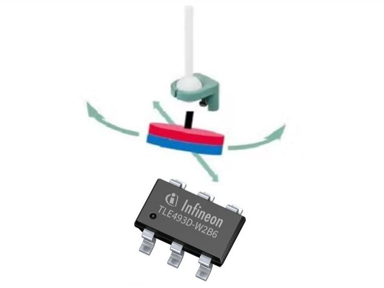
Basic Know-HowThere is a magnet embedded on the bottom of the joystick whose movement will cause a change in the magnetic field which will be detected by the TLE493D-W2B6 magnetic sensor present in the TLE493D-W2B6 S2Go kit.
Follow the steps below and your joystick will become smart !
1. SetupThe hardware is pretty simple! Just place the Shield2Go Adapter for Raspberry Pi on top of the Raspberry Pi and on top of it, place the sensor and joystick assembly and then you connect the four lines SDA, SCL, GND, VDD of the 3D magnetic sensor to the Shield2Go adapter and you're ready to go !
Next step would be to Initiate the communication between the RPi and Magnetic Sensor using I2C. Let's go deep on the communication part!
The User Manual for TLE-493D-W2B6 sensor describe the sensors’ register-map, I2C communication and steps involved very efficiently. On the par, let's walk through on doing it with the RPi!
First, we scan the I2C bus on the RPi using i2cdetect -y 1. We see the 7-bit address of our sensor as 35H. This we will use to start the I2C communication handle.
We use PIGPIO library in python to communicate via I2C. Generally, PIGPIO library is installed by default but if not, one could pip install, via pip install pigpio.
In order to use pigpio module in Python (remote GPIO for Raspberry Pi), pigpio Daemon (pigpiod) has to be loaded to memory on RPi. This also requires sudo privileges, thus, you have to enter following command in your terminal at every startup.
After this, we are ready to speak to our sensor ! We will be using jupyter notebook to ease process visualization of setting up the I2C communication between the sensor and the RPi.
In first block we import the pigpio library, then open the channel for I2C communication via handle, using following block of code.
For further writing and reading we just have to use this handle (h).
Also, do keep in mind that there are certain changes we need to make on the register level to initiate the I2C communication. The steps for the same are as listed below :
- Set PR bit in Mod1 register as High to enable 1-byte read mode. Failing to set this bit results in the sensor giving NACK for read requests on I2C or the register values are read as FFH.
- Enable clock stretching and disable /INT and collision avoidance by resetting the CA bit to Low and setting INT bit to High.
- Now set the mode to Master Controlled Mode by writing 01b to MODE bits
- IICAdr bits are left as 00b since the product type is A0.
- The FP bit value is set/reset according to the odd parity of the Mod1 register and the PRD bits of the Mod2 register, which in this case comes out to be 0b.
With these steps, the value to be written to Mod1 register becomes 15H.
- Now, set the TRIG in Config register as 10b, for we need ADC trigger on after reading the 05H register.
- Other bits in Config register are left as default as those enable the Temperature and Bz measurement.
With these steps, the value to be written to Config register becomes 20H.
We write these values to register of 3D magnetic sensor using write_byte api of the pigpio library as follows:
After this you can use an update function to keep on reading from the sensor, as follows:
Now we are set to draw and play using the obtained raw data from the sensor!
3. Make it 'Smart' with Machine LearningWe generated an image dataset from a polar plot using the magnetic field coordinates from the sensor as written on the code. Our dataset consisted of around 4000 images on each category of shape (Circle [C], Square [S], Triangle [T] and None of the mentioned[N]).
Using this dataset a Neural Network was trained on https://studio.edgeimpulse.com/. You can use Edge impulse to train your own dataset or even the same dataset as shown below :
- Click on the above link which will navigate you to Edge Impulse Studio. You'll have to create a free account on the same for starting your machine learning feat !
- Now create a new 'developer' project as shown :
- A window as shown below will pop up once you create the project. Since you are going to upload the generated images, you have to select 'images' in the list. Also, select 'Classify a single image' in the next window that pops up !
- Now, we see a pop up that asks for the data that is to be used for training. Since we already have the data available, we will use the uploader to upload it from the PC.
- Upload the category of images one after the other giving them respective labels by choosing the files and then click on 'Begin upload'.
- Click on 'Create Impulse' and set the dimensions of image as 32x32 (This can be any size but we are limiting the size here to reduce the processing requirement as the 'free developer mode' allows only as much ! ). Then add the processing block (select for Image) and the learning blocks (select transfer learning) and save the impulse !
- After you save the impulse, more options will open up for processing under the heading 'Impulse design' on the left. Select the image tab and on the color depth, select 'Grayscale' and click on 'Save parameters'. A new window will open up for generating features from the data where you just have to click on 'Generate features'.
- Now, select 'transfer learning' under the heading 'Impulse design' and alter the training parameters as required to train the model for best results and click on 'Start training'.
- Once the training is done, corresponding confusion matrix will be generated giving an indication of how well the model was trained.
- Now, Click on the 'Model testing' heading and test the model on the created test dataset by clicking on 'classify all' tab. The resulting accuracy will indicate how well the model learned !
- After testing, if you select the heading 'Dashboard', you'll be able to download the model in the desired format.
This is as much of Edge Impulse that you'll need for this project to work but if you need to know more, do checkout : https://docs.edgeimpulse.com/docs !
We found converting the trained Keras network model to tensorflow lite model worked better than using the tensorflow lite model itself. The converted tensorflow lite model along with the dataset we used is attached for your use. You can also use custom trained model by generating your own dataset, train it and use it!
4. Get-Set --> Ready -->Go!
To deep dive into our workaround, you just have to download the attached Requirements.txt and the 'Smart Shape Stick' zipped folder in the code section which contains the python Code for Smart Shape Stick, Trained Keras Model and the used dataset. Once downloaded on your Raspberry pi, you initially have to install the packages mentioned on the Requirements.txt. The links for guiding the package installations is also provided in the Requirements.txt. Now, you can make a folder containing the keras model (which is converted to tensorflow lite model) and the python code. You can open the python code on any of the platforms that support python such as Google Colab, Jupyter Notebook, Notepad++ or Visual Studio Code. We have used Visual Studio Code at our end ! Now, just run the program and draw the shape to see the shapes getting predicted by our Smart Shape Stick !
P.S. You need to be real fast while drawing the shape once the code starts running as the current version of the code is capturing only 1000 samples i.e., if you aren't fast the code will have only part of the image and not the whole ! Modifying the number of samples that are captured is another option if you want to be slow as a snail ! ;)
What to Expect ?
Have fun extending this application to other characters !! :)
Race on the TRACK !
- If you are new to Raspberry pi, then do have a look through this for getting you started :
- To know more on the Infineon sensors : https://www.infineon.com/cms/en/product/sensor/magnetic-sensors/
- For skimming through I2C implementation of Rpi : https://learn.adafruit.com/adafruits-raspberry-pi-lesson-4-gpio-setup/configuring-i2c


Comments