


Hardware components | ||||||
 |
| × | 1 | |||
Software apps and online services | ||||||
 |
| |||||
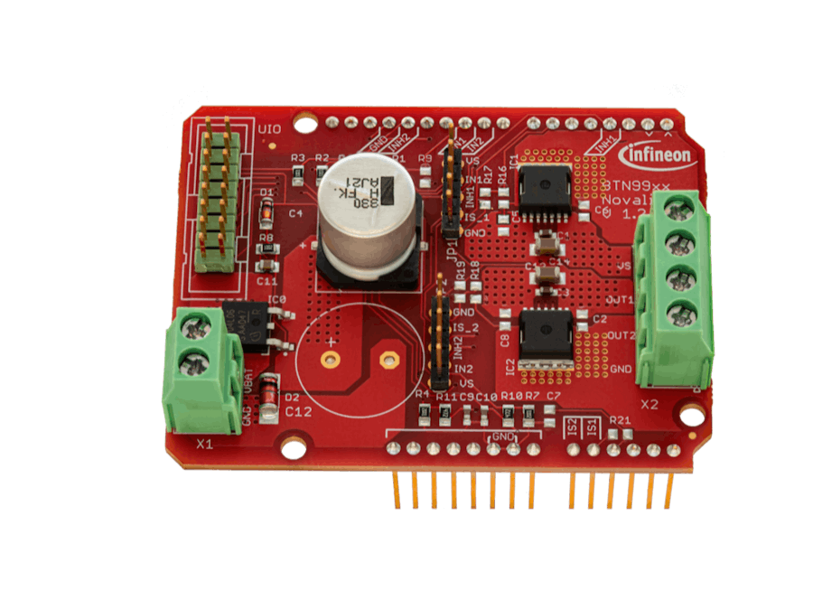
DC Motor Control Shield with BTN9970LV and BTN9990LV
Let us introduce the newest member of boards featuring our NovalithIC+™ family of products. The board comes with two high-current half bridges with integrated drivers, the BTN9970LV and BTN9990LV. The motor control shield with NovalithIC+™ is designed to drive DC motors in combination with an Arduino-compatible baseboard.
The shield can be easily controlled using the general logic IO-Ports of a microcontroller, such as an Arduino Uno R3, XMC1100 boot kit or similar controller. So go ahead, give it a spin and see what the NovalithIC+™ family can do for you!
Dissecting the shieldVS: Voltage Source
VBAT: Battery
GND:Ground
Out1: Output of the first half-bridge IC
Out2: Output of the second half-bridge IC
IN1: Input to the first half-bridge IC
IN2: Input to the second half-bridge IC
EN1: Enabling the first half-bridge IC
EN2: Enabling the second half-bridge ICIS1: Diagnosispin of Device 1 (BTN9990)
IS2: Diagnosispin of Device 2 (BTN9970)
The two half bridges on the shield can be used in a few different ways:
- You can use each one independently to drive two DC brushed motors in one direction.
- Or, you can combine them to create a single H (full)bridge that can drive a DC brush motor in both directions.
So, whether you want to control two motors separately or one motor that can go in both directions, these shield has you covered.
Closer LookBTN9970/BTN9990
Both the BTN9970 and the BTN9990 have the same chip design so their pinouts are identical! The differences between them however are the path resistance, overcurrent detection level, and the differential current sense ratio.
As you can see from the table above, we have two main input signals and two output signals on both ICs.
Let's take a look at the inputs:
- The first input signal (IN) that's received at pin number 3 is an analog signal that tells the motor driver: how much power we actually want to get delivered to the motor connected to it.
- The second input signal (INH) that's received at pin number 4 is a digital signal that activates the motor driver. (If the signal received is logic HIGH then the motor driver is activated, however, if the signal received is logic LOW then the motor driver will go to sleep).
Now that those are covered let's also have a look at the outputs:
- The first output signal OUT, which is sent out at pin 8 is essentially the analog signal that drives our output.
- The second output signal IS, which is sent out at pin 5 is a diagnostic signal sent by the driver in case of an error such as overtemperature or over current.
In this section, we'll go over some concepts that will help you understand how those shields actually operate!
Half Bridge Circuit
A half bridge is a type of electrical circuit that uses two switches (like transistors or thyristors) to control the flow of electricity through a load (like a resistor, inductor, or capacitor). You can think of it like a see-saw with a load in the middle: the switches can control whether the load gets electricity or not. Half bridges are used in a lot of different electronic devices, like power supplies and motor drives, because they can do things like switch power on and off, change AC voltage into DC voltage, and control the flow of electricity in a circuit. They have some advantages over other types of circuits, like being cheaper and using fewer parts, but they can also be less efficient and might need extra parts to protect them and keep them isolated.
As you can see from the pictures, we can control the direction of the current through the motor by flipping the green and red switches. If we open the green switch and close the red switch, the current will flow in one direction, and if we do the opposite (close the green switch and open the red switch), the current will flow in the opposite direction. This means that by changing the combination of open and closed switches, we have the ability to control which way the DC motor spins!
PWM
Pulse Width Modulation (PWM) is like a switch for your electronics. It turns the power on and off really fast, so we can control how much power goes to the device. We do this by changing the width of a square wave signal, which is a fancy way of saying we switch between high and low. By adjusting the width of the pulse, we can control how much power goes to the device.
PWM is used in lots of electronic stuff, like controlling the speed of motors, making LEDs shine brighter or dimmer, and even powering laptops and smartphones. It's a simple and effective way to control the power going to a device, and it can be easily set up with a microcontroller or other fancy electronic stuff
Installing the library for this shield very simple. All you have to do is to open your Arduino IDE and click on Sketch>Include Library>Manage Libraries, search for "motix" and install the "motix-btn99x0" library
Great job on installing the library! Now it's time to start using it. It's easy to get started - all you need to do is include the library in your code. Then you can start using the shield right away!
#include "btn99x0_motor_control.hpp"In C++, a namespace is a declarative region that provides a way to group related identifiers together. Namespaces are used to organize code and to avoid name collisions that can occur when multiple code modules define functions or variables with the same name. To ease our lives, we will be using the "using" command so that we could just use our functions instead of always writing the prefix "btn99x0::" before every function in the library.
using namespace btn99x0;Defined within the btn99x0namespace, is the 'DCShield' class. We will have to instantiate a DCShield classed variable.
DCShield shield;Moving forward we will fall into the ultimatum of choosing whether we want to control a motor bidirectionally or control the two half bridges respectively.
Half Bridge Control
The next step is to define a variable of type HalfBridge. To do this we use the constructor "get_half_bridge()". This constructor takes in as argument a constant value that determines which half-bridge are we dealing with.
for example:
The following snippet creates the variable half_bridge_one that would be associated with IC1 (BTN9990)
HalfBridge half_bridge_one = shield.get_half_bridge(DCShield::HALF_BRIDGE_1);The following snippet creates the variable half_bridge_two that would be associated with IC2 (BTN9970)
HalfBridge half_bridge_two = shield.get_half_bridge(DCShield::HALF_BRIDGE_2);To start using the shield our variable has to be initialized by using the begin() function. For example, if we wanted to initialize our half_bridge_one instance we would write:
half_bridge_one.begin();By default, the half-bridge is disabled when you use the begin() function. If you want to manually control the half-bridge, you can use the disable() and enable() functions to turn it on or off as needed. These functions make it easy to control the utilization of the half-bridge.
By default, the half-bridge is enabled when you use the begin() function. If you want to manually control the half-bridge, you can use the disable() and enable() functions to turn it on or off as needed. These functions make it easy to control the utilization of the half-bridge.
let's get started! To control the output, you have two options. You can either use the set_pwm() function and specify the duty cycle as a number from 0 to 255, or you can use set_pwm_in_percentage() and specify the percentage of the load that you want to output through the half-bridge. Both of these options are easy to use and will allow you to effectively deliver output.
for diagnosis you could get the temperature/current readings of the half-bridge ICs, however, you have to configure the dk and the k_TIS constants. (More information in the datasheet). To set those use the set_ktis(float ktis_amps_per_kelvin) and the set_dk(uint16_t dk) functions. Subsequently, you could use get_load_current_in_amps() and get_temperature_in_kelvin(). Both functions return a double data type with the respective value requested.
To check the status of your half-bridge, you can use the get_diagnosis() function. This function will return a value from an error code enum, which can either be:
- "NO_ERROR": represented by the enum value 0
- "FAULT_CURRENT_ERROR": represented by the enum value -1
- "INVALID_OPERATION_ERROR": represented by the enum value -2.
Motor Control
The next step is to create an instance of the MotorControl class, pass the shield instance to the constructor, and assign it to the btn_motor_control variable.
MotorControl btn_motor_control(shield);Moving forward, the next step for full control is to choose
The main function that has to be run is the begin() function; this function initializes the motor controller/both half-bridges.
btn_motor_control.begin();Following is the set_speed() function. This function enables the half-bridge outputs and provides a PWM with the given duty cycle to half-bridge 1 if the speed is positive, or to half-bridge 2 if the speed is negative.The input parameter to this function ranges between -255 and 255 where the input sign determines the direction and the value indicates the duty cycle.
ex: If we would like the motor to move with max duty forward.
btn_motor_control.set_speed(255);To stop the motor we have two options either to use the brake() or the freewheel().
Congratulations!This is the end of this protip! We hope you enjoyed reading it and feel more inspired to be creative with your projects. If you have any questions about anything that wasn't clear, don't hesitate to ask. And don't forget to check out our other protips and projects for more ideas and inspiration. Thanks for reading!


Comments
Please log in or sign up to comment.