


Hardware components | ||||||
 |
| × | 1 | |||
 |
| × | 1 | |||
 |
| × | 1 | |||
| × | 1 | ||||
 |
| × | 3 | |||
 |
| × | 1 | |||
 |
| × | 1 | |||
 |
| × | 1 | |||
Software apps and online services | ||||||
 |
| |||||
Hand tools and fabrication machines | ||||||
 |
| |||||
 |
| |||||
The Infineon maker community is getting into the spooky spirit this Halloween, and we're celebrating with a project that's sure to cast a spell on trick-or-treaters of all ages! Meet our Candy Dispenser: a 3D printed pumpkin with a radar-powered brain that detects when someone is lurking nearby, and then dispenses a sweet surprise from its glowing, toothy maw.
Want to learn how to bring this magical treat dispenser to life? Read on to discover the secrets of our spooky creation and get ready to impress your friends and family with a Halloween hack like no other!
The pumpkin contains two parts: the upper part, which will be filled with chocolate, and the lower part, which contains the dispensing mechanism and houses all the electronics. The pumpkin has a gear motor that powers a feed screw, which pushes the chocolate through the mouth of the pumpkin to be dispensed. The motor is triggered by a radar sensor that can detect when someone comes close to the pumpkin. Additionally, we have added Neo Pixel lights inside the pumpkin to make the eyes glow.
We used the Infineon XMC1400 2GO KIT as our microcontroller due to its flexibility and range of features, which allowed us to easily implement our design.
Dispensing MechanismThe first step for this project is to find a suitable dispensing mechanism that can also be fitted inside the pumpkin while still leaving space to fill it with chocolate. We started testing with a door mechanism that relies on gravity, but due to the compact size of the pumpkin and the high risk of malfunctioning, we eventually settled on a feed screw mechanism (Archimedes' screw) for more reliable dispensing.
The Infineon XMC1400 2GO KIT functions as the brain of the pumpkin, programmed to control the dispensing mechanism and lighting effects.
At the core of the dispensing mechanism is a 12V gear motor, which powers the feed screw. This screw efficiently pushes the chocolate through the mouth of the pumpkin for dispensing. The setup is powered by an external 12V power supply.
The gear motor is activated by a radar sensor, the Infineon S2GO RADAR BGT60LTR11, which detects when someone approaches the pumpkin. Upon detection, the radar sensor sends a signal to the XMC1400 2GO KIT microcontroller, triggering the gear motor to start the candy dispensing process.
To add a spooky effect, Adafruit NeoPixel Ring (WS2812 5050 RGB LED) is installed inside the pumpkin, making its mouth glow. These RGB LED rings can be programmed to display various lighting patterns, enhancing the visual appeal of the dispenser.
To address to the different voltage requirements of the components, the Infineon TLS412 is used to convert the 12V power supply to 5V. This 5V output is necessary for powering the XMC1400 2GO KIT microcontroller and the NeoPixel rings.
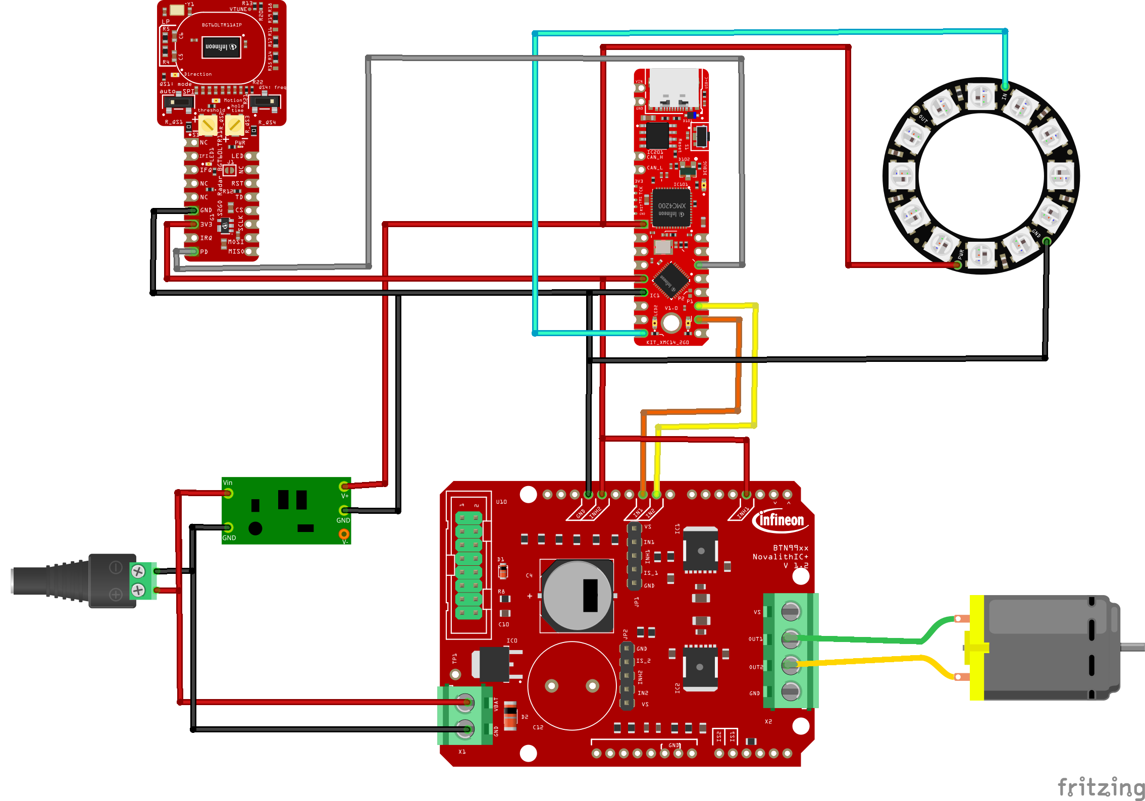
Schematics
The schematic of my project consists of several key components. At the center is the Infineon XMC1400 2GO KIT, a microcontroller unit (MCU) that boasts high performance and low power consumption and stands out with the very small size. To power the MCU, I have a 12V external power supply, which provides a stable and reliable source of energy. However, the XMC1400 2GO KIT requires a 5V power supply, so I used the Infineon TLS4120 5V CORE-BOARD to convert the 12V input to a stable 5V output. This conversion is crucial to ensure the MCU and the other components operate within its specified voltage range.
The radar module is connected to the XMC1400 2GO KIT, and requires the pin PD (presence detection), to be connected to the controller. This pin and the 3, 3V power supply as well ground connection are essential for enabling communication between the radar module and the MCU, allowing the system to process and respond to detection data. For a more in-depth look at the radar module and its capabilities, please follow this link to the corresponding Hackster article.
For motor control, I selected the BTN99XX0LV_Arduino_Shield, a versatile and easy-to-use platform. This shield is directly connected to the 12V power supply, which powers the motor control circuitry. However, to enable communication between the shield and the XMC1400 2GO KIT, we still need the 3.3V and GND pins from the MCU to the shield. This allows the two components to exchange data and control signals. The BTN99XX0LV_Arduino_Shield has two input pins IN1 and IN2 to receive control signals from the XMC1400 2GO KIT. The DC motor is now connected and powered between the pins OUT1 and OUT2. For a more detailed explanation check out this article.
Finally, I added an LED ring to the schematic, which is powered by 3V3 and GND. The LED ring is connected to the XMC1400 2GO KIT, and is controlled by a GPIO pin. This allows me to customize the behavior of the LED ring, creating a visually appealing effect that enhances the overall user experience.
3D printed parts and assemblyStep 1: Mounting the Motor
- We first mount the motor to the motor mount, ensuring it is securely attached with a significant amount of force to prevent it from coming loose.
- Then we attach the feed screw to the motor and secure it with an M3 12mm screw.
Step 2: Assembling the Inner Components
- We need to first insert the three parts into the inner part of the pumpkin.
- Then we pass the motor wire through the middle of the inner pumpkin.
- We secure the motor mount with a small axe (also a big screw can secure it ).
Step 3: Wire the Components and Assemble the Compartments
- Now we follow the provided schematics to wire all the components together.
- Once the wiring is complete, we place each component in its respective small compartment.
- To keep the electrical components in place, you can use double-faced tape to secure them.
- When wiring the radar component, better to use long wires to allow for easy mounting later. Make sure to keep the radar component outside of the compartments for now, as it will be mounted separately later.
Final Assembly and Preparation for Coding
- We now place the inner part of the pumpkin into the lower part of the shell.
- From the inside, we stick the radar component through the upper shell of the pumpkin.
- Now finally we close the pumpkin, making sure all parts are securely in place.
I have also placed in the design several 3 mm holes for attaching magnets - Pass the power supply wire through the hole in the upper shell of the pumpkin.
- Once everything is in place, close the pumpkin and you're ready to start coding!
Note:
- The radar component has a red LED indicator that shows its status. When the LED is red, it means the radar is not detecting anything. When it detects something, the LED will turn off.
- To adjust the radar's sensitivity, use the left potentiometer. You can increase or decrease the sensitivity based on the distance you want to detect from. This will help you fine-tune the radar's performance to your specific needs.
- Sometimes, the system may experience jamming due to the not very steep angle of the inner part that holds the chocolates. This can cause the dispensing to malfunction.
The code uses the radar sensor to detect movement and trigger the motorized mechanism to dispense treats. The software also controls the NeoPixel lights to create a spooky ambiance.
1. Getting started with Arduino IDE and XMC Boards
For this, check our documentation to help you install Arduino IDE and the XMC Boards!
2.Installing the library
To ensure the Adafruit_NeoPixel library supports the XMC1400 2GO KIT, a modification must be made in the Adafruit_NeoPixel.cpp file. Specifically, on line 2339, XMC1400 2GO KIT must be added. This changes the line from
elif defined(XMC1100_XMC2GO) || defined(XMC1100_H_BRIDGE2GO) || defined(XMC1100_Boot_Kit) || defined(XMC1300_Boot_Kit)to
elif defined(XMC1100_XMC2GO) || defined(XMC1100_H_BRIDGE2GO) || defined(XMC1100_Boot_Kit) || defined(XMC1300_Boot_Kit) || defined(XMC1400_XMC2GO)3. Code Includes and Definitions
We start by including the necessary header files and defining constants and variables that we'll use throughout the code. We include three header files: btn99x0_motor_control.hpp, btn99x0_half_bridge.hpp, and Adafruit_NeoPixel.h. The first two headers are custom files for motor control and half-bridge control, respectively, while the third is a library for controlling NeoPixel LEDs. We then define several constants, including radarswitch, HB1_IN, HB2_IN, HB1_INH, and HB2_INH, which are related to the half-bridges and motor control. Additionally, we define NEO_PIN as the digital pin for the NeoPixel LED strip and SPEED as a constant for the motor speed
#include "btn99x0_motor_control.hpp"
#include "btn99x0_half_bridge.hpp"
#include <Adafruit_NeoPixel.h>
using namespace btn99x0;
#define radarswitch 0
#define HB1_IN 1 // PWM Pin for DC-Shield
#define HB2_IN 2 // PWM Pin for DC-Shield
#define HB1_INH 3 // Inhibit PIN for Halfbridge 1 on DC shield
#define HB2_INH 4 // Inhibit PIN for Halfbridge 2 on DC shield
#define HB1_Isense A1 // Diagnosis pin for Half-bridge 1
#define HB2_Isense A0 // Diagnosis pin for Half-bridge 2
#define NEO_PIN 3 // NeoPixel pin
#define SPEED 150
Motor Control and NeoPixel Setup
Next, we set up the motor control and NeoPixel LED strip. We create two half-bridges, hb1_io_pins and hb2_io_pins, and a motor control object, btn_motor_control, using the DCShield class. This setup is necessary for controlling the motor. We also set up a NeoPixel LED strip with 8 pixels on pin NEO_PIN. This LED strip will be used to provide visual feedback during the dispensing process.
io_pins_t hb1_io_pins
{
HB1_Isense,
HB1_IN,
HB1_INH
};
io_pins_t hb2_io_pins
{
HB2_Isense,
HB2_IN,
HB2_INH
};
hw_conf_t hw_conf =
{
2000, // Resistor on the DC shield for the Diagnosis pin
3.3,  // Maximum voltage on the ADC Pin
1023
};
DCShield shield(hb1_io_pins, hb2_io_pins, hw_conf);
MotorControl btn_motor_control(shield);
Adafruit_NeoPixel neoPixel = Adafruit_NeoPixel(8, NEO_PIN, NEO_GRB + NEO_KHZ800);
int previousradarvalue = 0; // Previous radar sensor value
unsigned long lastPulseTime = 0; // Time of the last pulse
Setup Function In the setup function, we initialize the serial communication, motor control, and NeoPixel LED strip. This function is called once at the beginning of the program. We initialize the serial communication at 9600 baud, print a message to the serial console, and delay for 5 seconds. This allows the system to settle and ensures that the serial communication is established before proceeding. We then initialize the motor control object, set the slew rate to level 7, and initialize the NeoPixel LED strip. This prepares the motor and LED strip for use in the dispensing process.
void setup() {
Serial.begin(9600);
Serial.println("Serial initialized");
delay(5000);
btn_motor_control.begin();
delay(2000);
// Set the slew rate
btn_motor_control.set_slew_rate(SLEW_RATE_LEVEL_7);
neoPixel.begin();
}
Dispense Function The dispense function is responsible for controlling the dispensing process. It's called when the digital pin 5 is high. We start by printing a message to the serial console indicating that we're dispensing. We then set the first NeoPixel to yellow, show the color, and delay for 500ms. This provides visual feedback that the dispensing process has started. We then set the first NeoPixel to red, show the color, and delay for 500ms. This provides additional visual feedback during the dispensing process. We then run the motor control in a loop, alternating between positive and negative directions, with short delays in between. This controls the motor to dispense the desired amount. Finally, we stop the motor and turn off the NeoPixel, and delay for 3 seconds to allow the system to settle.
void dispense() {
Serial.println("Dispensing...");
neoPixel.setPixelColor(0, neoPixel.Color(255, 255, 0)); // Yellow
neoPixel.show();
delay(500);
neoPixel.setPixelColor(0, neoPixel.Color(255, 0, 0)); // Red
neoPixel.show();
delay(500);
for (int i = 0; i < 2; i++) { // Dispense motor control
btn_motor_control.set_speed(-SPEED); // Turn motor in positive direction
delay(400); // Short delay
btn_motor_control.set_speed(+SPEED); // Turn motor in negative direction
delay(100); // Short delay
}
btn_motor_control.set_speed(0); // Stop the motor after dispensing
neoPixel.setPixelColor(0, neoPixel.Color(0, 0, 0)); // Turn off NeoPixel
neoPixel.show();
delay(3000);
}
Loop Function In the loop function, we read the digital pin 5 and call the dispense function if the pin is high. This allows the dispensing process to be triggered by an external signal.
void loop() {
int radarValue = digitalRead(5); // Read from digital pin 5
if (radarValue == 1) {
dispense(); // Run the dispense function when pin 5 is 0
}
}Congratulations on completing your interactive pumpkin project! We hope you had a blast building it and can't wait to see what kind of spooky magic you'll create with it.
Trick Part Alert!
As a bonus, we've added a small mount in the upper shell of the pumpkin, just waiting for your creative touch. Why not take your pumpkin to the next level by adding a servo motor to move a skeleton behind the pumpkin? The possibilities are endless, and we can't wait to see what kind of trickery you'll come up with!
Happy Halloween!
Thanks for joining us on this project, and happy hacking! May your Halloween be filled with spooky fun and creative spirit!


Comments