


Hardware components | ||||||
_ztBMuBhMHo.jpg?auto=compress%2Cformat&w=48&h=48&fit=fill&bg=ffffff) |
| × | 1 | |||
 |
| × | 1 | |||
Software apps and online services | ||||||
 |
| |||||
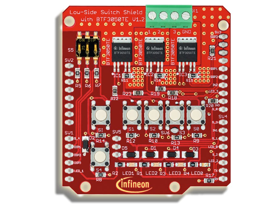
Discover the power of efficient control with Infineon's Low Side Shield. This Arduino-compatible Shield features three BTF3050TE low-side switches, enabling control over three power channels. Perfectly compatible with the Arduino form factor and ARM® powered XMC™ microcontroller kits from Infineon. The Shield's star component, the BTF3050TE, is an integrated single-channel low-side switch with an N-channel power MOSFET and comprehensive protection features. Optimized for 12V automotive and industrial applications, this Shield paves the way for effortless control in your projects. Let's explore how to use this remarkable tool.
What is a low side switch?Before diving deep into the main topic or the protip that is about to be shared, it's worthwhile to understand a foundational concept that will make the main topic clearer.
Low Side Switch - A Closer Look:
Basic Definition: A low side switch is a component in an electrical circuit. Its primary function is to make or break a connection, similar to how a regular switch allows you to turn on or off a light in your room.
Position in the Circuit: The term "low side" indicates its position in relation to the circuit. Specifically, a low side switch is positioned between the active component and the ground.
Active Component: This is the main component in the circuit that performs a specific function when powered. For instance, an LED will emit light, and a motor will start spinning.
Ground: This is a reference point in an electrical circuit from which voltages are measured. It's also a return path for electric current. Connecting components to ground ensures they operate safely and effectively.
Why Use a Low Side Switch? By placing the switch between the active component and the ground, we can control the operation of the active component by either connecting or disconnecting it from the ground. The low side switch can offer certain advantages in various scenarios, such as simplifying circuitry or enhancing safety.
How to use/connect a low side switch?Once you've attached the shield to your microcontroller, simply link the ground segment of your circuit to the shield's ground pin. This setup allows you to connect and individually control up to three devices via the shield's output.
For example in the diagram above we are controlling a DC motor over output 1.
BTF3050TE ChipThe main component of the shield are the 3 low side switch chips, let's have a look at their structure and break down their pins :)
- IN Input pin. This pin takes in the switch control signal from the microcontroller
- VDD 5V supply pin This pin takes in power that is used in powering up the shield's onboard components
- OUT Drain, Load connection for power MOSFETThis is the pin connected to the Output pin of the shield and therefore connected to the active component.
- SRP Slew rate adjustment and digital status feedback 5
Adjusting the slew rate is not performed by the micro-controller, rather by connecting a resistor to the SRP pin. Shorting the SRP pin to GND represents the fastest switching speed. Open SRP pin represents the slowest switching speed. In the shield, the SRP of each of the three chips is connected to a 5K resistor.
- GND Ground
Let's delve into the chip to understand its signal processes. The microcontroller's input signal directs the gate driving unit, which is then modulated by both the INput signal and the output from the Slew Rate adjustment unit.
In the provided diagram, the input of the MOSFET is determined by the subsequent signals. For clarity, the MOSFET (Metal-Oxide-Semiconductor Field-Effect Transistor) on the right side of the diagram is a type of transistor used to amplify or switch electronic signals and electrical power. The chip also has other functions such as:
- Overtemperature Protection
- Overvoltage Protection
- Short Circuit Detection/Current Limitation
This means that in case of an overtemperature-, an overvoltage- or a short circuit event, the BTF3050 chip will not conduct.
ShieldAside from the actual low side switch chips, the shield contains a lot of input devices that could be used to control the behavior of the shield. These devices include:
- 3 Way DIP Switch: A DIP switch (an acronym for "Dual In-line Package" switch) is a commonly employed electrical switch in electronics. Its primary use is to select different operating modes or configurations without the need for soldering. With the 3 Way DIP Switch present on the shield, users can choose among multiple preset configurations swiftly, tailoring the shield's behavior to their specific needs.
- 6 Buttons:These tactile buttons can serve a multitude of purposes, from sending specific commands to the shield to cycling through different operational states. The flexibility of having multiple buttons means you can set up different triggers or actions.
Note: For those using an Arduino Uno, it's crucial to note that S_I cannot be utilized as it isn't physically connected to the Arduino pins.
- 4 LEDs: LEDs (Light Emitting Diodes) on the shield typically act as indicators. They can show the status of specific operations, signify which mode the shield is currently in, or simply act as visual feedback in response to user actions. For example, an LED might light up when a particular button is pressed or when a specific configuration on the DIP switch is active.
With these input devices, the possibilities are vast. Users can craft intricate control schemes, develop intuitive user interfaces, and even debug their projects more effectively.
SoftwareThe software part of using this shield is very straightforward! All we have to do is address the pins of the elements we want to use and speak to each pin individually.
Pin Definitions
To ease the process of dealing with the signals, you can insert this code snippet into your code at the very beginning of it.
#define LED_0 4
#define LED_1 A4
#define LED_2 2
#define LED_3 10
#define DIP_1 A1
#define DIP_2 A2
#define DIP_3 A3
#define PWM_1 6
#define PWM_2 11
#define PWM_3 9
#define S_0 8
#define S_1 5
#define S_2 3
#define S_3 7
#define S_4 A0
#define SRP_1 13
#define SRP_2 12
#define SRP_3 A5
This makes programming easier since instead of remembering what the pin number is, you could just use these pin definitions.
Setting Up the pins
Copy the following code snippet into the setup function:
pinMode(LED_0, OUTPUT);
  pinMode(LED_1, OUTPUT);
  pinMode(LED_2, OUTPUT);
  pinMode(LED_3, OUTPUT);
  pinMode(DIP_1, INPUT);
  pinMode(DIP_2, INPUT);
  pinMode(DIP_3, INPUT);
  pinMode(S_0, INPUT);
  pinMode(S_1, INPUT);
  pinMode(S_2, INPUT);
  pinMode(S_3, INPUT);
  pinMode(S_4, INPUT);
  pinMode(SRP_1, INPUT);
  pinMode(SRP_2, INPUT);
  pinMode(SRP_3, INPUT);
This tells our microcontroller what to expect, when dealing with those physical connections. (Are we going to send or receive signals on these lines.)
In the code snippet above the SRP pins are set to input, however during error handling we will have to actively change the pin mode of the SRP pins to output. (Don't worry we will talk more about this later!)
Controlling the BTF3050 Low Side Switch
In the previously mentioned "Pin Definitions" section, the pins for the low side switches have been designated as PWM_1, PWM_2, and PWM_3. To interface with the BTF3050 switches, simply send pulse width modulated (PWM) signals to these pins.
PWM signals dictate two main things to the switches:
- Whether the switch should be open or closed.
- The amount of power from the network to be delivered through the load.
For instance, to fully close switch 1 and allow maximum power flow through it, incorporate the following code:
analogWrite(PWM_1, 255);To let through only half the power, use:
analogWrite(PWM_1, 128);Error Handling
In case of an Over-temperature event: the error is indicated by a high-logic active fault signal on the respective SRP pin.
In order to continue using the shield you have to reset the chips. The following code snippet resets all three onboard BTF3050 chips:
pinMode(SRP_1, OUTPUT);
pinMode(SRP_2, OUTPUT);
pinMode(SRP_3, OUTPUT);
digitalWrite(SRP_1, LOW);
digitalWrite(SRP_2, LOW);
digitalWrite(SRP_3, LOW);
//Delay while micrcontroller is still running to ensure the chip had enough time to react.
for(int32_t i; i<160000;i++) {}
pinMode(SRP_1, INPUT);
pinMode(SRP_2, INPUT);
pinMode(SRP_3, INPUT);
Using the Onboard LEDs
To use the LEDs: all you'll have to do is send logic HIGH and LOW signals to the LED pins to respectively turn them on or off. For example if you'd like to turn them all on you could just copy this into your loop function:
digitalWrite(LED_0,HIGH);
digitalWrite(LED_1,HIGH);
digitalWrite(LED_2,HIGH);
digitalWrite(LED_3,HIGH);
Using the onboard buttons
Using the onboard buttons is the exact same as using the LEDs, except we're not sending logic signals, we're actually receiving them. So instead of using the digitalWrite function, we will be using digitalRead function.
For example if we want to read the button S_1 we could use the following code:
if(digitalRead(S_1)){
  digitalWrite(LED_1,HIGH);
}
This code snippet will keep LED 1 on as long as button 1 is pressed.
Using the DIP Switch
The DIP switch is essentially just a switch between a logic HIGH connection and the microcontroller pin. All what we need to do is just read that pin. For example if we would like to just read the three DIP switch outputs in our program we could just write this in the loop:
// Reading the values of DIP switches
  int dip1Value = digitalRead(DIP_1);
  int dip2Value = digitalRead(DIP_2);
  int dip3Value = digitalRead(DIP_3);

// Print the values of the DIP switches serially
  Serial.print("DIP_1: ");
  Serial.println(dip1Value);
  Serial.print("DIP_2: ");
  Serial.println(dip2Value);
  Serial.print("DIP_3: ");
  Serial.println(dip3Value);
  Serial.println("----------");
(Note if you were to use the previous code snippet in your loop function, you'll have to setup a serial communication between your microcontroller and your interface (for example PC) by putting this into your setup function:
Serial.begin(9600);This just initializes a serial connection with a baud rate of 9600.
Conclusion:
With the BTF3050TE Shield in hand, here's a quick rundown of your newfound capabilities:
- Understanding of Low Side Switches: You've grasped the basics of what a low side switch is and its function in a circuit.
- Harnessing the BTF3050TE Chip: Not only do you know about the chip's significance, but you can now effectively use its pins to manage power control.
- Control over Three Power Channels: With the shield's three BTF3050TE low-side switches, you can individually control up to three devices.
- LED Manipulation: Turn on and off onboard LEDs with straightforward commands.
- Button Interaction: Understand how to read signals from the shield's buttons and use them in your projects.
- DIP Switch Utility: You can read the DIP switch outputs to set operating modes for your devices.
- PWM Control: Efficiently manage power delivery by using pulse width modulated signals.
- Error Handling Capabilities: You're set to address issues like over-temperature by using the shield's fault detection mechanisms.
In short, you've unlocked a world of precise and efficient control in your electronic projects. Dive in, experiment, and let the Infineon's Low Side Shield enhance your creations. Happy tinkering!


Comments
Please log in or sign up to comment.